
Specifications


Galaxy 5000 technical specifications
MGE UPS SYSTEMS SPTC5 500 UK – 09/2005 page
14
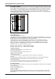
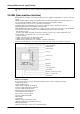
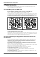
Free-frequency chopping
The regulation system for the output voltage uses the free-frequency PWM (pulse width modulation) technique
shown in figure 9. The chopping frequency, used to remain within the tolerances of the reference sinusoidal
wave, is higher in zones with significant variations where the regulation must react more quickly. It also takes
into account the load behaviour. Individual regulation of each phase that controls IGBT on and off times.
Using this regulation technique, the inverter output impedance remains very low, thus ensuring a high-quality
output voltage and improving the overall efficiency.
Modulation
t
U ref
U ref + U
U ref - U
High chopping
frequency
Lower chopping
frequency
Large
variation
Small
variation
Fig. 9. Operating principle of free-frequency chopping.
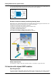
Sixpack IGBT modules
Use of sixpack IGBT modules ensures:
Reliability of the converter : significantly higher than what is obtained with standard IGBTs. This is based on
operational observations, and explained by the reduction in the number of components, and the control boards
directly soldered on the Sixpack. (suppression of cable and connection)
Smaller dimensions for an equal power rating, thus enhancing access and reducing the footprint
Better EMC (electromagnetic compatibility) performance due to closer positioning of functions (PFC,
inverter, static switch, etc.) that reduces wiring inductances. The standard EMC level "C3 - monitored
distribution" guarantees compatibility with severe environments and compliance with the IEC 62040-2
standard. The "C2 - class A" level is available on option.
Output characteristics - high-quality voltage
Voltage and frequency
380, 400 or 415 V AC at 50 Hz; by default 400 V, 50 Hz
380 or 400 V AC at 60 Hz
These two parameters may be personalised by the user.
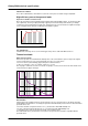
Voltage accuracy and setting
Steady-state accuracy
± 1% of rms values of phase-to-neutral and phase-to-phase voltages and of peak values.
Setting
The output voltage is adjustable using the fine setting on the UMI in the Un ± 3% range, which makes it
possible to take into account voltage drops due to long cables downstream of then UPS.
Transient performance
± 2% for load step changes from 100% to 0 and 0 to 100% (loads turned on or off).
The return to the ± 1% range (rms values) takes place in less than 100 ms.
Low voltage distortion
The low distortion level means all types of loads are possible, including linear, capacitive and non-linear (RCD
as per ENV 50091-3).
Phase-to-phase distortion < 2%
Phase-to-neutral distortion < 3 %
Frequency stability
The speed of inverter frequency variation can be user set to 1 Hz/s or 2 Hz/s. This protects sensitive loads
from the rapid frequency variations in bypass AC power when the inverter output frequency is synchronised
with the latter.