w w w. m g e u p s .
Installation and User Manual Epsilon STSTM 200A and 400A/600A Static Transfer Switch Installation and User manual Revision History Epsilon STS 200A and 400A/600A STS, Installation and User Manual Revision: A00 B00 B01 B02 B03 Initial Release ECN: 002866 ECN:#003777 ECN:#004471 ECN:#004991 86-12345-00 B02 06/2002 09/2002 03/2004 07/2005 10/2006 Copyright © 2005 MGE UPS SYSTEMS, INC. All rights reserved. Printed in U.S.A. MGE UPS SYSTEMS, INC.
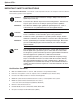
Epilson STSTM IMPORTANT SAFETY INSTRUCTIONS SAVE THESE INSTRUCTIONS – This manual contains important instructions for the Epsilon STSTM that must be followed during operation of the equipment. WARNING Opening enclosures expose hazardous voltages. Always refer service to qualified personnel only. ATTENTION L'ouverture des cabinets expose des tensions dangereuses. Assurez-vous toujours que le service ne soit fait que par des personnes qualifiees.
Installation and User Manual WARNING To reduce the risk of fire or electric shock, install in a temperature and humidity controlled indoor area free of conductive contaminant’s. This equipment is intended only for installations in a RESTRICTED ACCESS LOCATION. ATTENTION Pour réduire le riske d'inccendie ou d'électrocution, installer dans une enciente intérieure contrôlée en température et humidité et sans contaminant’s conducteurs.
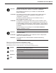
Epilson STSTM CAUTION: Record All Serial Numbers! RECORD ALL SERIAL NUMBERS FOR THE Epilson STSTM AND COMPONENTS. THESE SERIAL NUMBERS WILL BE REQUIRED IF YOUR SYSTEM NEEDS SERVICE.
Contents section description . . . . . . . . . . . . . . . . . . . . . . . . . . . . . . . . . . . . . . . . . . .page Revision History . . . . . . . . . . . . . . . . . . . . . . . . . . . . . . . . . . . . . . . . . .i IMPORTANT SAFETY INSTRUCTIONS . . . . . . . . . . . . . . . . . . . . . . .ii Certification Standards . . . . . . . . . . . . . . . . . . . . . . . . . . . . . . . . . . . .ii How to use this manual and Symbol Usage . . . . . . . . . . . . . . . . . . . .
Epilson STSTM Section 2 Setup and Installation section 2.0 2.1 2.2 2.3 2.4 2.5 2.6 Section 3 Scope . . . . . . . . . . . . . . . . . . . . . . . . . . . . . . . . . . . . . . . . . . . . .2 — 1 First steps by an on-site qualified Technical Engineer . . . . . . . .2 — 1 Final steps by MGE Field Service Engineer . . . . . . . . . . . . . . . .2 — 1 Required Equipment and Tools . . . . . . . . . . . . . . . . . . . . . . . . . .2 — 1 Cabinet Placement and Environment . . . . . . . . . . . . . . . . . . .
Installation and User Manual Section 3 Operation section 3.4.6 3.5 3.6 3.7 3.8 3.9 3.10 3.11 3.12 3.13 3.14 3.15 (continued) description . . . . . . . . . . . . . . . . . . . . . . . . . . . . . . . . . . . . . . . . . . .page EPO . . . . . . . . . . . . . . . . . . . . . . . . . . . . . . . . . . . . . . . . . . . . . . .3 —6 Preferred Source Selection (Symmetrical Operation) . . . . . . . . .3 —6 Sensing and Transfer Times . . . . . . . . . . . . . . . . . . . . . . . . . . . . .
Epilson STSTM Figures figure description . . . . . . . . . . . . . . . . . . . . . . . . . . . . . . . . . . . . . . . . . . .page QS-1 QS-2 QS-3 QS-4 QS-5a QS-5b Positioning of 200A Epsilon STS™. . . . . . . . . . . . . . . . . . . . . .QS —2 Positioning of 400/600A Epsilon STS™ . . . . . . . . . . . . . . . . . .QS —3 200A STS Input/Output Power Connections. . . . . . . . . . . . . . .QS —4 400/600A STS Input/Output Power Connections. . . . . . . . . . . .QS —5 200A STS . . . . . . . . . . . . . . . .
On-Site Quick Start CAUTION Scheduling of the MGE Field Service Engineers typically should be done 7 to 10 days before they are required on-site. If the startup of the UPS is critical to maintaining your schedule, please call the MGE toll free telephone number at 1-800-438-7373 for assistance. Final installation and start-up should be completed by a qualified MGE Field Service Engineer.
Epilson STSTM Step 1 Unpacking Once the Epsilon STSTM UPS System has been inspected and received from the shipping courier, the unit should be moved with the use of a fork lift or pallet jack to a position as close to the final installation location as possible. Prior to any installation, the following items should be observed upon receipt of the Epsilon STSTM 10-30 kVA UPS. 1. Inspect shipment for any damage prior to receipt. Damage claims should be filed directly with the courier.
Installation and User Manual Figure QS-2 Positioning of 400/600A Epsilon STS™ LEVELING JACKS CASTERS OPTIONAL SEISMIC BRACKETS SECURED USING 3/8 BOLT 86-504004-00 B03 Quick Start QS —3
Epilson STSTM Step 2 Connection of Utility Power Inputs Connect Input Power from Two Sources The Epsilon STS™ systems provides for either top or bottom cable entry. Connections are to be made with 75°C copper wire cables and using the lugs supplied with the STS unit. Refer to section 2.0 Installation and/or the system installation drawing(s) for more details (such as cable size and number of conductors).
Installation and User Manual Figure QS-4 400/600A STS Input/Output Power Connections. CONTROL WIRE PANDUIT/WIRE-WAYS TOP ENTRY CONDUIT PLATE COMMUNICATION CARDS CONTROL WIRES THREADED THROUGH UNIT TB1 TERMINAL CONTROL WIRE PANDUIT/WIRE-WAYS BRACE AT 12" INTERVALS CONTROL WIRES BOTTOM ENTRY CONDUIT PAN Step 4 Arrival of MGE Field Engineer The MGE Field Engineer will finalize the initial Epsilon STS™ start-up.
Epilson STSTM Optional Steps Should you require AC power on site prior to the arrival of the MGE Field Engineer, the following procedure will provide the AC power in the bypass mode. Should you have any questions about this procedure, do not hesitate to contact MGE Customer Support. A. Ensure that all switches, CB1-5 in the STS are open (off). B. Apply input power to the source S1 input of the STS by closing the upstream circuit breaker for source S1. The STS controls will power up and issues alarm(s).
Introduction 1.0 Scope Introduction is a general description of system characteristics of Epsilon STSTM, its intended use and applicable electrical, mechanical and environmental specifications. 1.1 Reference Manuals 160304-00 C00 JBUS/RS232, Installation and User manual. 1.
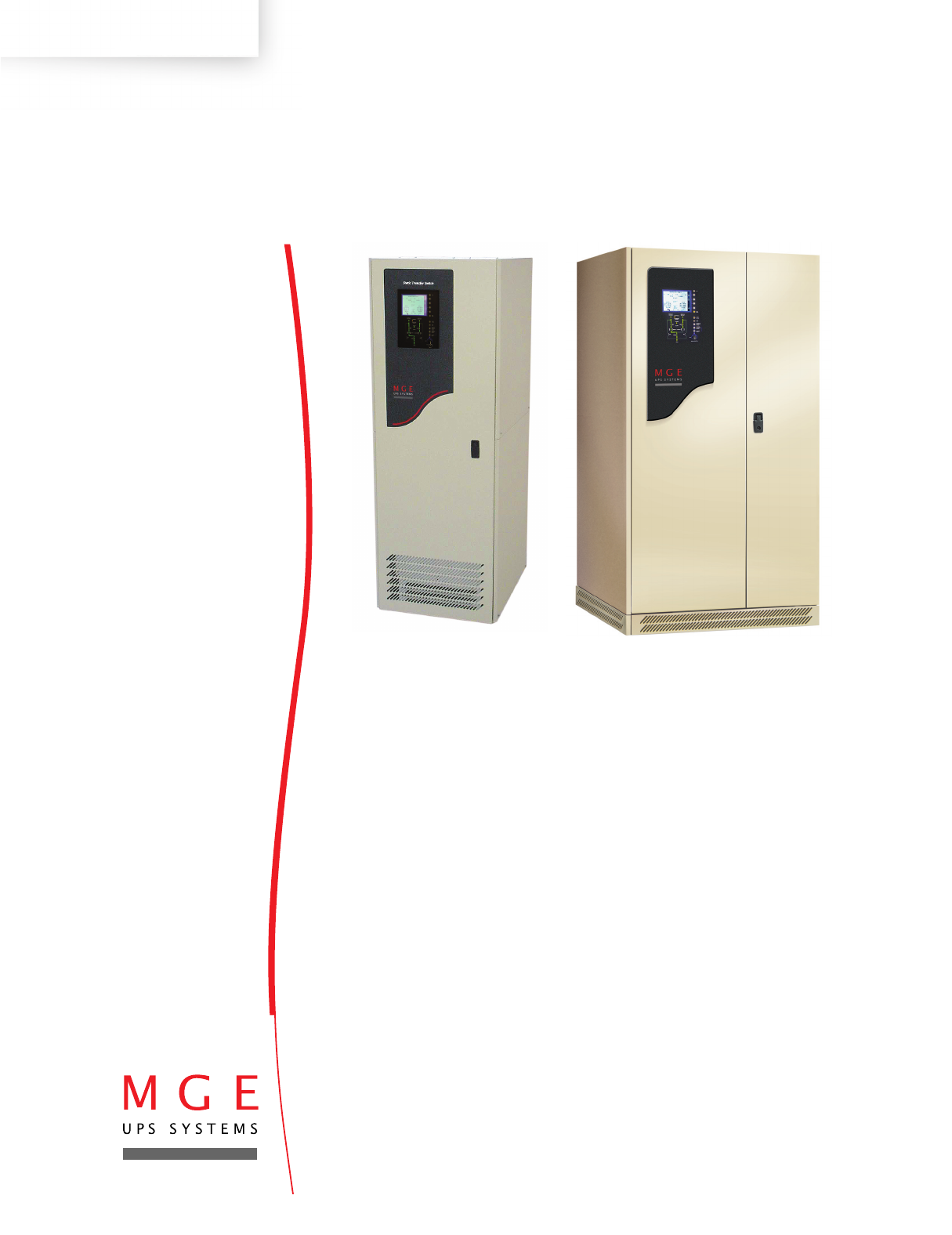
Epilson STSTM 1.3 General Description The Epsilon STS™ system is available in two different cabinet sizes. Dimensions for the cabinets are: ◗ 200A cabinet: 72”H x 24”W x 30”D ◗ 400A/600A cabinet: 72”H x 38”W x 30”D Both cabinets are designed to provide for top and/or bottom entry of input and output power feeds. The Epsilon STS™ system can be purchased to accept 208 VAC, 220 VAC, 240 VAC, 440 VAC, 480 VAC, 575 VAC or 600 VAC utility feed. Figure 1-1a: Epsilon STS™ - 200A Cabinet.
Installation and User Manual 1.4 Epsilon STSTM System Characteristics The Epsilon digital Static Transfer Switch (STS) is a solid state, three-phase, break-before-make, dual position switch designed to connect a critical three-phase load to one of two separate, independent, synchronized sources of three-phase power. The STS consists of six pairs of SCR's connected in an AC switch configuration.
Epilson STSTM 1.4.1 PMM2 Plus and PMM2 Ultra In the PMM2 Plus configuration, the input of the PMM2 cabinet is supplied by the output of the STS. The dual input distribution system accepts two independent AC input sources feeding to the STS. If the preferred input source power is not available, the STS will transfer to the alternate input source, avoiding interruption to the critical load.
Installation and User Manual 1.5 System Major Components Source #1 CB1 Input isolation molded case switch with magnetic trip for isolating SCR static switch #1 and associated components from source S1. Source #2 CB2 Input isolation molded case switch with magnetic trip for isolating SCR static switch #2 and associated components from source S2. Output CB3A Output isolation molded case switch with magnetic trip for isolating both static switch sections from the load.
Epilson STSTM Front Display Panel Comprised of a 4.7” x 3.6” LCD with associated “soft” keys for monitoring status, alarms, changing certain settings and performing certain operations; an LED “mimic” diagram display for indicating switch status and power flow; and manual control pushbuttons for manual transfer functions. Hard Keys Manual, dedicated keys (pushbuttons) that have a single function.
Installation and User Manual 1.6 Single Line Diagram During normal operation, CB1, 2, 3A and 3B (if installed) are closed and the load receives power from the designated preferred source through either SW1 or SW2 SCR switch. In the event of a preferred source failure, the STS will transfer the load to the alternate source in a fraction of a cycle. If bypassed by closing either CB4 or CB5 bypass switch, CB1, 2, 3A and 3B (if installed) are opened, isolating the static switch section for maintenance.
Epilson STSTM 1.7 1.7.1 1—8 System Specifications Recommended environment 20° to 25°C (68° to 77°F); 50% relative humidity; computer room or other temperature and humidity-controlled environment. Operating temperature 10° to 40°C (50° to 104°F). Storage -10° to 60°C (-14° to 140°F). Humidity up to 95% non-condensing (operating). Altitude sea level to 8,500 feet without derating. Acoustic noise 65 dBA typical at rated load as measured 5 feet from the front of the STS module.
Installation and User Manual 1.72 Electrical Cable Access and Connections Electrical connections and other cabinet interconnection will vary depending upon the configuration and options selected with your Epsilon STS™ system. Refer to the installation drawings supplied with your equipment. CAUTION: Before making any electrical connections, verify that all circuit beakers are in the "off" position. Customer-supplied upstream protective devices and distribution circuits should be OFF.
Epilson STSTM 1.7.4 Accessing Electrical Connections CAUTION: Only an authorized electrical professional should access electrical connections. A severe shock hazard exists. The ONLY user serviceable items in the Epsilon STS™ unit are: A. The input power connections B. The load connection C. Any wire connections to the customer control terminal block. D.
Installation and User Manual Figure 1-6: 400/600 STS Power and Control Wire Connections. TOP ENTRY CONDUIT PLATE CONTROL WIRE PANDUIT/WIRE-WAYS COMMUNICATION CARDS CONTROL WIRES THREADED THROUGH UNIT. TB1 TERMINAL CONTROL WIRE PANDUIT/WIRE-WAYS BRACE AT 12" INTERVALS CONTROL WIRES BOTTOM ENTRY CONDUIT PAN Table 1-2: Input/Output Power Connections. STS # OF CABLES PER MINIMUM CABLE LUG CONDUIT CABLE SIZE (75°C, CU) (SUPPLIED) HOLE DIA. (QTY.
Epilson STSTM (This page left blank intentionally) 1 — 12 86-504004-00 B02
Setup and Installation 2.0 Scope Setup and Installation guides the User through tools and equipment required for making hardwire connections. Included are power cable connections with wire diagrams for configuring the product to specifications, and obtaining MGE field service assistance for final installation and startup. Final installation and start-up should be completed and performed by a qualified MGE Field Service Engineer.
Epilson STSTM 2.1 Cabinet Placement and Environment The complete STS system may consist of more than one cabinet depending on whether the STS is a stand-alone unit or it is used in conjunction with input isolation or output distribution cabinets such as the Power Management Module2 (PMM2) cabinets. Cabinets must be arranged in the required positions to ensure proper connections.
Installation and User Manual 2.2.1 Conduit Plate Location (bottom entry) Cable entry through the bottom is the standard preferred design for the Epsilon STS™ cabinet. Please see the following figure for the location of the bottom entry conduit plate. Figure 2-2: 200A /400/600A STS Cabinet Footprint and Top View. 200A STS REMOVABLE CONDUIT PAN 10.0 X 7.0 OPENING REMOVABLE CONDUIT PLATE 8.3 X 8.
Epilson STSTM They should not pass near interference-emitting equipment or sensitive loads. Complete wiring instructions for your installation are provided on the installation drawings supplied with the equipment. 2.3.3 Remote Emergency Power Off (REPO) Cable Connections Control connections are available for “Remote Emergency Power Off” (REPO) through a customer-supplied normally open dry contact or pushbutton. a) Connect the emergency power off N.O.
Installation and User Manual 2.3.5 Connection of the Relay Communication Card The relay communications card contains six programmable dry contact outputs and two programmable dry contact inputs, and is standard on the Epsilon STS™. The inputs and outputs are factory programmed according to functions listed in Table 2-2. Table 2-2: Relay Contacts (communications card) Inputs Factory Setting 1.A - Select Source S1 as Preferred. 1.B - Select Source S2 as Preferred. Note: 1. 2.
Epilson STSTM 2.3.6 Characteristics of the Output Contacts Relay type Max. voltage Max. current Cable Normally Open. 250VAC, 30VDC. 2A. 4 x 18 AWG, cover plate hole diameter 0.26 inch ± 0.01 inch Figure 2-4: Output Contacts. 6 5 4 3 2 1 B A 2.3.7 Characteristics of the Input Contacts Switched voltage Consumption Cable 5 VDC. 10 mA. 4 x 22 AWG, hole diameter 0.2 inch ± 0.
Installation and User Manual 2.3.8 Removing the Communications Card Cover a) Remove the cover “3” secured by the screws “1”. b) Run the communications cables through the cable entry holes “4”. c) Connect the conductors to the input “6” and output “5” terminal blocks (see connection example in diagram below). Figure 2-5: Removing the Communications Card Cover. 1 2 3 2 4 1 BA 6 2 3 4 1 6 5 5 6 BA 2 3 4 5 6 5 4 3 7 2.3.
Epilson STSTM 2.4 Setting Operation Mode Set DIP switch SA1 for one of the following configuration modes: First Card Second Card (optional) Standard Mode (default) Standard Mode (default) All switches OFF SA1 switch 1 ON SA1 SA1 8 8 1 ON 1 OFF ON OFF First Card Second Card (optional) Programmable Mode Programmable Mode SA1 switch 3 ON SA1 switches 1 & 3 ON SA1 ON SA1 8 8 1 1 OFF ON OFF Figure 2-7: SA2 and Dip switch location on communication card.
Installation and User Manual 2.5 Setting the Output Relay Contacts and Input Switching States Set DIP switch SA2 for one of the following configuration modes: N.O. Setting (default) All switches OFF SA1 8 1 ON OFF N.C. Setting All switches ON SA2 8 N.C. NOTE: By default, all the relay contacts are Normally Open (NO) (see section 1.4): ◗ Contact open = relay not controlled. ◗ Contact closed = relay controlled.
Epilson STSTM 2.5.1 Connection of the JBUS Communication Card The JBUS communications card provides two DB-9 ports (RS232 and RS485 communications). Only one communication port may be used at a time. For information on using the communication card, see the JBUS communication card manual. Figure 2-8: JBUS Communication Card. 5 4 9 3 8 2 7 RS232: Pin 2: Rxd (or Txd) Pin 3: Txd (or Rxd) Pin 5: Com (shield) S ODBU JBUS/M RS485: JBUS Pin 4: RxPin 5: Tx- 2.
Operation 3.0 Scope Operation describes Epsilon STSTM system characteristics of indicators and controls, startup and shutdown procedures, safety checklists, modes and specifications and theory of operating the Epsilon STSTM system. 3.1 Preparation for Operation Several items must be considered when preparing the Epsilon STS™ system for operation. Configuration The STS cabinet and any auxiliary cabinets (such as PMM cabinets containing power distribution panels, transformers, etc.
Epilson STSTM 3.2.1 Normal Start Up Procedure With all of the initial safety check points verified, the Epsilon STS™ system can now be powered. The following procedure should be used after the Epsilon STS™ system has been commissioned (typically by an MGE Field Service Engineer). 1. Ensure that all switches, CB1, 2, 3A, 3B(if installed), 4 and 5 in the STS are OFF (open). 2. Energize both input sources and check for correct voltage, phase rotation and source synchronization.
Installation and User Manual 3.2.2 Post Start Up Safety Check List After initial start up of the system, normal operation of the STS should be verified. At the minimum, the following should be checked as applicable to your installation: ◗ Remote emergency power off (REPO) operation (all switches in the STS should trip off). After this test, reset all switches in the OFF position and repeat the start up procedure. ◗ Maintenance bypass procedure.
Epilson STSTM 3.3 Transfer Operations 3.3.1 Automatic Transfers Automatic transfer of the load from one source to the other is accomplished by turning off the active source SCR's and turning on the inactive source SCR's in a sequence and timing that allows a combined sense and on transfer time of less than one quarter cycle (4.17ms).
Installation and User Manual 3.3.4 Transfer Authorization/Prohibition Transfer is prohibited under the following conditions: a) Transfer Prohibit Input from the operator control panel, control contact input, or communications port. b) Peak Current Overload. c) External Power Fault (peak current overload caused by undervoltage) - Memorized. d) Overtemperature (active or inactive switch) - Memorized. Reset fault from alarm menu. If the fault persists, call MGE Customer Service.
Epilson STSTM 3.4.5 Live System Test (Except with 4-Interlock System) While in maintenance bypass, and with the STS output isolation switch off, the STS can be tested with both sources connected to the STS through the input isolation switches (using the SCR's to make actual transfers). 3.4.6 EPO In the event of an Emergency Power Off (EPO) condition, all switches are shunt tripped. 3.
Installation and User Manual 3.9 Open SCR Protection The STS design includes sensing circuits to detect an open SCR and in addition to the following actions, will initiate audible and visual alarms: In the event of an open SCR in the active source powering the load, the unit will alarm and immediately transfer to the inactive source. Then the SCR isolation switch on the previously active source will be shunt tripped.
Epilson STSTM Bypass Load to Source #2 1. The Source #2 SCR Switch #2 must be indicated closed on the display panel. If not, transfer the load to Source #2 by turning the Manual Control key switch on the front display panel to the “ON” position and pressing the Change Preferred Source Pushbutton. The STS should transfer to Source #2. 2. Open Source #1 isolation switch, CB1. (For 4-interlock system, lock and remove the key). 3. Lock Source #1 bypass switch, CB4, and remove the key. 4.
Installation and User Manual 3.12 Front Panel The Epsilon STS™ system is simple to operate and yet provides a wealth of continuous monitoring and diagnostic features to insure the proper operation of the unit. Operators gain access to information in the Epsilon STS™ system through the operator interface. This display panel and keyboard is conveniently located on the front of the STS cabinet. (See Figure 3-1, page 3-10).
Epilson STSTM 3.13 Front Display Interface Panel Figure 3-1: Front Display Interface Panel. ? NORMAL OPERATION A 2A B 0 KW 1A C 1 KVA HELP 3A ! PF 0.0 Preferred UPS 1 UPS 2 A-B 503 V B-C 501 V C-A 507 V volt A-B 504 V B-C 503 V C-A 508 V Synchro 60.0 HZ 60.
Installation and User Manual Figure 3-2: LCD Normal Operation Screen Visual/Audible Alarms -access separate screen to view alarms. Load Meters -Current (ØA, B, C) -KVA -KW -Power Factor (PF) NORMAL OPERATION A 200A B 200A 133 KW C 200A 166 KVA Preferred Source Indication 0.8 PF Preferred Source S1 V1 480V V2 480V V3 480V Source S2 Name (field programmable) Source S2 Synchro 60.0 HZ V1 480V V2 480V V3 480V 60.
Epilson STSTM Figure 3-3: Manual Operation Pushbuttons. Alarm Silence pushbutton Lamp Test pushbutton - always active - silences audible alarm horn - turns on all LEDs on the front panel - sounds the audible alarm horn ALARM SILENCE Return to Preferred Source pushbutton - temporarily enables auto-retransfer when retransfer function is switched off (re-transfer disabled) and initiates a retransfer back to the preferred source, overriding the owner selected auto retransfer time delay.
Installation and User Manual Figure 3-4: LED Mimic Diagram. SOURCE #1 SELECTED AS PREFERREDYELLOW LED SOURCE #1 AVAILABLE GREEN LED-LIT WHEN SOURCE #1 POWER IS APPLIED TO SOURCE S1 INPUT SOURCE #2 SELECTED AS PREFERREDYELLOW LED SOURCE 1 AVAILABLE SOURCE 2 AVAILABLE S1 S2 SOURCE #2 AVAILABLE GREEN LED-LIT WHEN SOURCE #2 POWER IS APPLIED TO SOURCE S2 INPUT PREFERRED SOURCE SOURCE #1 INPUT C.B.
Epilson STSTM 3.14 Operator Interface Screens The screen displays contained on the Epsilon STS™ Operator Interface provide an easy to use method to access and control the STS features. A screen saver feature will blank out the LCD screen after the Epsilon STS™ has been in continuous operation for a while. Figure 3-5: LCD Display Screens. Initial screen Main screen NORMAL OPERATION A 2A B 1A 0 KW MAIN MENU C 3A Transfer 1 KVA PF 0.0 UPS 1 A-B 503V B-C 501V C-A 507V 60.
Installation and User Manual 3.15 Epsilon STS™ Customization Certain parameters can be customized as follows: 1. Press the
Product Name (This page left blank intentionally) 3 —16 86-504004-00 B02
MGE Warranty & Proprietary Rights Statement for Three Phase Products (Applicable within the United States, Canada and Mexico) MGE Standard Three Phase Warranty MGE UPS SYSTEMS, INC.
Warranty and Product Registration Thank you for choosing MGE UPS SYSTEMS, INC. for your power protection, distribution, and quality requirements. We are pleased to have you join our increasing family of users. In order to maximize the value you receive from this product, and to ensure that you are kept informed of product or software updates, we recommend that you take a few minutes to register your new purchase. You may register online at the URL noted below.
MGE Customer Care Center - Three Phase Products Technical Support and Product Services ? Technical questions? If you encounter a problem while following the instructions in this manual, or have questions about the operation, repair, or servicing of your equipment, please direct calls to MGE UPS SYSTEMS, INC. Customer Care Center or visit our web site www.mgeups.com for complete service information.
Product Name (This page left blank intentionally) W—4 86-504004-00 B02
Glossary Term used Definition / Meaning @ At. / And/or. +/- Plus or Minus. ≤ Equal to or less than. # Number. °C Degree Celsius. °F Degree Fahrenheit. Ø Phase angle. Ω Ohm; unit of resistance. ® Trade Mark. 2nd Second. AC or ac Alternating current, also implies root-mean-square (rms). Ambient Temp. Temperature of surrounding air. Ambient noise Acoustical noise of surrounding environment. ANSI American National Standard Institute. AWG American Wire Gauge.
Epilson STSTM G—2 Current rating The maximum current that a conductor or equipment can carry reliably without damage. dBA Decibel Adjusted. dBrnC Decibel above reference noise. DC or dc Direct current, or voltage. Digital Meter The LCD display on the front panel of inverter system. Earth ground A ground circuit that has contact with the earth. Electrician Refers to an installation electrician qualified to install heavy-duty electrical components in accordance with local codes and regulations.
Installation and User Manual NFPA National Fire Protection Association. NO. or No. Part number. On-line mode Inverter output power is the primary energy source to load. Off-line mode Inverter output is off, and the load connected at the inverter output receives power from utility line via a static transfer switch or maintenance bypass relay. OSHA Occupational Safety and Health Agency. PCA Printed circuit assembly. PCB Printed circuit board. PWM Pulse Width Modulation.
Epilson STSTM (This page left blank intentionally) G—4 86-504004-00 B03
Reorder Form 1660 Scenic Avenue Costa Mesa, CA 92626 Use this form to report any errors, omissions, or other problems you have experienced, or to order additional hardcopies of this document. A free copy of this document may be downloaded from the proprietary MGE Rep Web site. Please contact your MGE UPS SYSTEMS, INC. Representative for assistance.
w w w. m g e u p s . c o m Contact MGE United States MGE UPS SYSTEMS 1660 Scenic Ave. Costa Mesa, CA 92626 Tel: (714) 557-1636 (800) 523-0142 Fax: (714) 557-9788 email: info@mgeups.com www: mgeups.com Canada MGE UPS SYSTEMS #9, 2789 Thamesgate Drive Mississauga, ON L4T 4E8 Tel: (905) 672-0990 (877) 672-0990 Fax: (905) 672-7667 email: info@mgeups.com www: mgeups.com Latin America and Other International MGE UPS SYSTEMS 1660 Scenic Ave. Costa Mesa, CA 92626 Tel: (714) 513-7831 (800) 523-0142 ext.