
User manual


86-86000-00 B02 - Page 43
2. Setup and Installation
2.9 Connection of Optional CLA Module
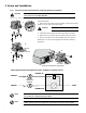
1. Connect the battery power cable
40
and battery detection cable
42
(provided with the CLA Module) between
the Power Module and the CLA Module.
2. Connect the DC Input of the CLA Module to high power battery cabinet.
DC Input Cable cross-section (not provided): maximum 4 AWG solid or stranded wire. z
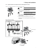
3. Connect the utility AC input to terminal blocks L1 and L2 of the CLA.
AC input cable cross-section (not provided): maximum 16 AWG solid or stranded wires. z
Field wiring connections to terminal block shall be made using the following:
– No. 14 AWG, 60ºC copper wires for AC inputs.
– No. 10 AWG, 75º C copper wires for DC inputs.
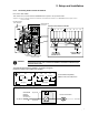
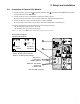
Figure 2-17: Rear view of CLA Module cable battery and AC input connections
DC Input to
High Power
Battery Cabinet
Separate, 15 A Utility
AC Source
@ 208 or 240
Use 15 A DBL. Pole CB
42
40
Connection Diagram
(inside CLA Module)
- +
DC INPUT
240 Vdc
N L
(L2) (L1)
AC INPUT
156-280 Vac
Terminal tightening torque:
– 5 lb-in. for AC input terminals
– 18 lb-in. for DC input terminals