
User manual


86-86000-00 B02 - Page 40
2. Setup and Installation
2.7.3 Connections with Separate Normal and Bypass AC Sources (2 Mains)
CAUTION
This connection requires isolation Transformer Module. Please visit our web site
www.eaton.com or call (800) 356-5794.
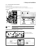
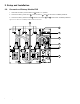
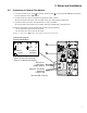
Figure 2-14: Normal AC and Bypass AC inputs, Output Cables Installation, and Simplified Connection Diagram.
4
1
3
Output
Bypass
Normal
OFF
O
OFF
O
OFF
O
To Load or
Transformer Module (if applicable)
2
L3
L1
MAINS 2
BYPASS AC
NORMAL AC
MAINS 1
LOAD
With separate Normal and Bypass AC inputs, supplied by separate sources.
Isolation
Tr ansformer
(PN 86211)
NOTE
Please visit our web site www.eaton.com or call (800) 356-5794 for assistance with sepa-
rate, normal AC, and bypass AC input support.
NOTE
With parallel redundance connection, two input transformers are needed for separate,
normal, and AC bypass input. Please visit our web site www.eaton.com for details.
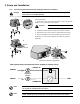
Proceed as follows:
1. Remove the cover plate under the I/O Box. Loosen the terminal
blocks L1 and L3, and remove the jumper.
CAUTION
Always connect the earth ground wire first.
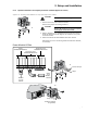
2. Install Normal AC, Bypass AC and output cables as shown.
3. Reinstall the cover plate under the I/O Box with four screws.
4. Secure the I/O Box to the Power Module with three screws.
See Section 2.7.2 for connecting EX RT Transformer module, if
applicable.