
User manual


86-86000-00 B02 - Page 39
2. Setup and Installation
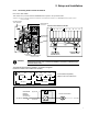
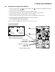
2.7.2 Connecting EX RT Transformer Module
Part number 86211/86311
This module is to provide isolated 120/208/240 VAC outputs to the protected loads.
Figure 2-13: View of EX RT Transformer Module connected downstream for 120/208/240 Vac outputs (shown
with one EXB).
POWER MODULE
EX RT 5/7/11
TRANSFORMER
MODULE EX RT
AC NORMAL
INPUT
TRANSFORMER MODULE
OUTPUT TO LOAD
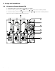
Terminal Block Transformer Module Connection diagram
(located on bottom of Transformer I/O Box)
L3 L2 L1 Lb Ld N Lc La
208 VAC
240 VAC
AC Input
120 VAC
208 VAC
AC Output
120 VAC
240 VAC
Te rminal Block capability:
AWG 4 solid or stranded wire.
BATTERY MODULE
EX RT EXB 5/7/11
AC INPUT
UPSTREAM
CIRCUIT
BREAKER
(NOT SUPPLIED)
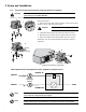
Transformer Module
Bypass AC
Normal AC
Simplified Connection Diagram
To Load
WARNING To avoid overloading 120 VAC output windings, distribute loads evenly
between Load 2 and Load 4 (on rear of Tr ansformer Module) and between
120 VAC output terminals (Lb-N, La-N.)
AC Input from
Power Module
(208 VAC shown)
AC Output to Load
(120 VAC shown)
L3 L2 L1 Lb Ld N Lc La
Transformer Module I/O Box
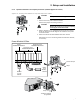
WARNING
To avoid overloading 120 VAC output windings, distribute loads evenly between
Load 2 and Load 4 (on rear of Transformer Module) and between 120 VAC output
terminals (Lb-N, La-N.)
Terminal Block T ransformer Module Connection diagram
(located on bottom of Transformer I/O Box)
L3 L2 L1 Lb Ld N Lc La
208 VAC
240 VAC
AC Input
120 VAC
208 VAC
AC Output
120 VAC
240 VAC
Terminal Block capability:
AWG 4 solid or stranded wire.
AC INPUT
UPSTREAM
CIRCUIT
BREAKER
(NOT SUPPLIED)
Transformer Module
Bypass AC
Normal AC
Simplified Connection Diagram
To Load