
User manual

86-86000-00 B02 - Page 18
1. Introduction
1.3 Rear Panel Components
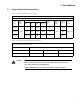
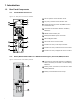
1.3.1 Power Module EX RT 5/7/11
Figure 1-3: Rear panel of the Power Module.
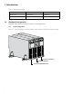
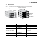
1.3.2 Battery Module EX RT EXB 5/7/11 With Remote Emergency Power Off (REPO) Function
Figure 1-4: Rear Panel of the Battery Module.
13
12
14
1
Slot for optional communication cards.
2
Dry (relay) contacts Communication Port.
3
Remote Emergency Power Off (REPO function.
(See Section 2.6.)
4
Connector for automatic detection of Battery
Module(s).
5
RS232 communication port.
6
Battery/CLA Module power connector.
7
Manual Bypass switch.
8
Normal AC source circuit breaker.
9
Knockout for entry of AC Output conduit.
10
Knockout for entry of Normal AC source conduit.
11
Knockout for entry of Bypass AC source conduit.
12
Connectors for automatic detection of additional
battery module(s) (to the UPS or to other Battery
Modules).
13
Battery power connectors (to the UPS or to other
Battery Modules).
14
Battery Circuit Breaker with shunt trip.
1
3
2
6
7
8
44
5
9
10
11