
Instruction Manual

Step 1
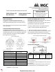
WIRING
Figure 4 WIRING TAPS
FOR MODELS WITH STROBE FEATURE,
STROBE INPUT POWER (NAC)
SELECTABLE SPEAKER POWER (WATTS)
Note: Connect speaker line between C
and desired wattage
Note: This device should be installed as per applicable
requirements of the authorities having jurisdiction.
Use the information in this document to determine the
total power or current of the devices. The total power or
current of the devices must not exceed the output rating of
the panel. Refer to the FACP installation guide for the wire
size required according to the loop length and devices
power usage. For maximum strobe operating current,
please refer to Table 5.
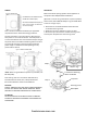
Figure 5 DEVICE CONNECTION
*Note: When using with Mircom panel or sync module, use
MP-300 (3.9K).
Note: Wiring must be in accordance with CSA C22.1,
Canadian Electrical Code, Part I, Safety Standard for
Electrical Installations section 32 and NFPA 70.
CAUTION
FOR ALL TERMINAL TAPS USED FOR SYSTEM SUPERVISION,
DO NOT USE LOOPED WIRE UNDER TERMINALS. BREAK
WIRE RUN TO PROVIDE SUPERVISION OF CONNECTIONS.
ATTENTION
NE PAS UTILISER DE FILS EN BOUCLE SOUS LES BORNES.
OUVRIR LA LIGNE POUR CONFIRMER LA SUERVISION DES
CONNEXIONS.
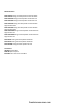
MOUNTING
MGC recommends spacing speaker strobe appliances in
compliance with CAN/ULC S524 and NFPA72.
(Optional. In case of using a standard 4” square 2 1/8 deep
electrical box, attach MP-184 adaptor ring from SPKC-W kit
to the unit using 4 snaps.)
1. Attach the unit to the IB-104 electrical box with the
2 included mounting screws.
2. Rotate the top cover clockwise to snap it in place.
3. Secure the top cover with the included securing screw
and snap the nameplate over the securing screw.
Figure 6 MOUTING DIAGRAM
Top cover
2 screws for attaching
device to IB-104
(Device with optional
adaptor ring)
Step 2
Securing screw
Nameplate
firealarmresources.com