
Instruction Manual

25 Interchange way, Vaughan, Ontario. L4K 5W3
Phone: 905.660.4655; Fax: 905.660.4113
Web: www.mircom.com
LT-6916 Rev 1.1 Jan 22, 2021
INSTALLATION AND MAINTENANCE INSTRUCTIONS
SPPS-104 Series [H] Ceiling Speaker-Strobe
SPP-104 Series Ceiling Speaker
ABOUT THIS MANUAL
This manual is included as a quick reference for
installation. For further information on the use of this
device with a FACP, please refer to the panel’s manual.
Note: This manual should be left with the owner/operator
of this equipment.
SPEAKER/SPEAKER STROBE DESCRIPTION
The SPPS-104 speaker-strobe is designed to meet
UL1480/ULC S541 requirements for speakers and UL1638
/ULC S526 requirements for visual notification appliances.
The SPP-104 speaker is designed to meet UL1480/ULC
S541 requirements for speakers.
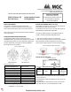
Figure 1 MODEL FRONT
SPPS-104 Series SPP-104 Series
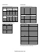
Table 1 SPECIFICATION
Operating temperature
0⁰C to 49⁰C
(32⁰F to 122⁰F)
Humidity range
0% to 93%
Strobe flash rate
1 Hz (1 flash per sec.)
Nominal strobe voltage
Regulated 24VDC/VFWR*
Operating voltage range
16-33 VDC/VFWR
Nominal speaker voltage
25V or 70.7Vrms
Speaker Size
4”
Power Setting
¼, ½, 1, 2 W
Speaker Frequency range
400 -4000 Hz
Terminal wire gauge
12-22 AWG
*Note: For FWR signaling use a Mircom panel.
SETTING THE CANDELA (SPPS series only)
The candela can be set to 15, 30, 75, 110, 125, 15/75 for
SPPS-104-25 and SPPS-104-70 models.
The candela can be set to 50, 75, 90, 130, 185, 15/75 for
SPPS-104-25H and SPPS-104-70H models.
The factory default setting is 15 for SPPS-104-25/70
models, and 50 for SPPS-104-25H/70H models.
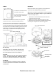
1. Pull out the candela selector from the device.
2. Re-insert the selector tab into the notch that is labeled
with the desired candela setting (when removing or
inserting the candela selector, ensure to keep it straight).
Figure 2 INSERTING CANDELA SELECTOR
SETTING THE DIP SWITCHES
Figure 3 DIP SWITCH
Table 2 DIP SWTICH
DIP
OFF
ON
Switch 1
Input*
Synchronized
Regulated
24VDC/FWR
(Non-sync.)
*Note: Use “SYNC” when flash synchronization is required,
either through a sync module or built-in synchronization
on the control unit.
Use “NON-SYNC” when the appliances do not need to be
synchronized.
Note: DIP switch 1 default setting is OFF, synchronized.
Note: DIP switch 2 is not used. By default it is OFF.
CAUTION / ATTENTION
DO NOT PAINT OR ALTER
FACTORY APPLIED FINISH IN ANY WAY
NE PAS PEINDRE OU MODIFIER
LA FINITION ORIGINALE
firealarmresources.com