
Owner Manual
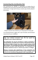
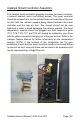

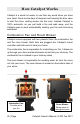

Table Of Contents
- Introduction
- Table of Contents
- Safety Precautions
- Features and Specifications
- Stove Installation
- Planning the Installation
- Stove Placement Requirements
- Standard Installation
- Corner Installation
- Chimney Requirements
- Chimney Connector Requirements
- Chimney Termination Requirements
- Special Installation: Exterior Factory-Built Chimney
- Special Installation: Masonry Chimney
- Special Installation: Masonry Fireplace
- Installing the Soapstone
- Connecting the Combustion Fan
- Connecting the Smart Sensors
- Initial Curing
- How Catalyst Works
- Catalyst Smart App
- Regular Maintenance and Troubleshooting
- Monthly Maintenance
- Annual Maintenance
- Catalytic Combustor Replacement
- Lifetime Limited Warranty

Catalyst Owner’s Manual | © MF Fire 2017 Page | 22
Catalyst Smart Controller Assembly
The Catalyst smart controller assembly includes the smart controller,
4 ceramic spacers, and 4 self-drilling screws. The smart controller
should be screwed in to the four piloted holes on the bottom of the rear
air duct with the ceramic spacers being placed between the smart
controller and the rear air duct. The screws should not be over
tightened in order to avoid damaging the ceramic spacers. The three
temperature sensors should be plugged into their respective ports
(TC1, TC2, TC3). TC1 and TC2 will already be installed in your stove
with the yellow connectors hanging out of the rear air duct. Refer to the
Catalyst Owners Manual for further information on the temperature
sensors. NOTE: If the location of the combustion fan for your
installation is such that the smart controller needs to be moved farther
up the rear air duct, new pilot holes can be made or an extension cord
can be requested from info@mffire.com.