
Operating instructions

APPENDIX B: ASSEMBLING LOUDSPEAKER CABLES
30
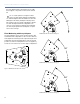
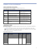
6. Solder the five exposed conductors to the five pins on the EN3 cord connector using the following wiring scheme.
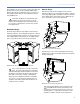
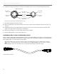
7. Reassemble the EN3 5-pin female connector:
■ Align the coupling ring’s side notches with the cord connector’s side notches and slide the couple ring onto the cord
connector.
■ Carefully insert the end of the cable clamp housing into the cord connector until it locks into place. Snap the cable
clamps in the cable clamp housing into their compartments.
■ Slide the boot forward so it covers the cable clamp housing completely.
8. Verify the wiring polarity is correct for both cable ends.
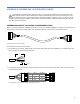
ASSEMBLING EN3-TO-EN3 LOUDSPEAKER CABLES
When connecting loudspeakers equipped with EN3 connectors to the MPS-488HPe power supply, you need an EN3 5-pin
female to EN3 5-pin male cable. The following procedure documents how to assemble this cable. If you are starting with an
EN3-to-pigtail cable, you can skip step 5 in this procedure.
NOTE: Cable mount connectors cannot connect to other cable mount connectors. Cable mount connectors
can only connect to panel mount connectors (like those on the MPS-488HPe) or inline connectors. To extend
cables with EN3 connectors on both ends you can use an EN3 5-pin female-to-male cable coupler.
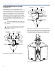
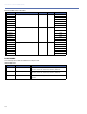
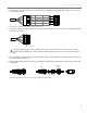
Pin Destinations for EN3 5-Pin Female Cable Mount Connector
Pin 5, White,
audio (+)
Pin 4, Blue,
audio (–)
Pin 2, Red,
48 V DC (+)
Pin 1, Black,
48 V DC (–)
Pin 3, Shield drain,
audio shield
Pin 5, White,
audio (+)
Pin 4, Blue,
audio (–)
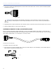
REAR
FRONT
Dimple identifies Pin 1
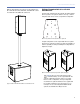
Assembled EN3-to-EN3 Cable