Operating Instructions HM-1S Self-Powered Studio Monitor Patents Pending Copyright © 1998 Meyer Sound Laboratories, Inc. All rights reserved Part # 05.059.004.
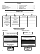
Contents Introduction .......................................................... 3 Power Requirements ............................................ 3 Power Cable Requirements .................................. 5 Audio Input ........................................................... 5 The HM-1S Subwoofer ......................................... 5 Cooling and Fan Installation ................................ 16 Protection and Limiting ....................................... 16 Safety Summary ...............
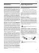
Introduction Power Requirements The Meyer HM-1S Studio Monitor is a compact, fullrange, self-powered reference monitor that employs a concentric tweeter mounting structure to achieve true point-source performance. Sophisticated phase-correction circuitry provides superb imaging without the off-axis cancellation effects, back-wave interference, and IM distortion commonly exhibited by dual-concentric speakers.
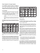
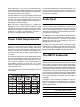
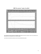
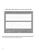
Power Supplies for Larger Systems If an installation includes more than 10 speakers, or requires several speakers to operate from a single 48 V line, a single, high-output power supply should be considered. The following sections provide current and voltage specifications for the HM-1Ss power requirements. Current Ratings The wide dynamic range of audio signals normally causes a high peak-to-RMS ratio in an amplifiers DC supply currents.
audio interruption. In the third, and preferable case, supplies that feature voltage foldback allow brief periods of current-limit without audio interruption; for this reason, we recommend using such supplies. A single HM-1S attached to a 100 ft 18 AWG cable (1.27 Ω total) produces a 6.4 VDC loss at the speaker (41.6 V) during maximum audio bursts (5 A, 0.5 s). This results in a small loss in peak SPL.
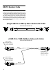
HM-1S Speaker Cable The following drawings and procedures are provided as an aid in the event that the speaker cable used to connect the HM-1S to the HM-1S Subwoofer needs to be repaired or extended. In cases where the original speaker cable has been modified, be sure to complete the Subwoofer Performance Verification section on page 10 of this manual. Misalignment of the polarity between the HM-1S and the HM-1S Subwoofer will result in a serious degradation of performance.
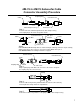
HM-1S to HM-1S Subwoofer Cable Connector Assembly Procedure Boot Coupling Ring Cable Cable Clamp Housing Cord Connector Contact Pins Step 1: Feed the end of the cable through the boot, cable clamp housing, and coupling ring in the order and position shown. Cord Connector Cable Dot pin 1 indicator 3/8" Max.
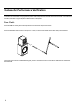
Subwoofer Performance Verification There are two methods of verifying that the phase relationship between the HM-1S and its subwoofer. One method is free field, the other is a ground plane measurement in half space. Free Field: Place the HM-1S directly above and coplanar to the subwoofer as pictured below: Place a calibrated measurement microphone 1 meter, on axis to the tweeter of the HM-1S as pictured below: Using the noise or other broadband test signal, perform a transfer function of the HM-1S.
HM-1S on axis at 1 meter, free field. This represents a typical response of the HM-1S in free-field environment, on axis at 1 meter. This measurement was performed in the large anechoic chamber at MSLI. Connect the subwoofer and measure the combined response of the system.
HM-1S with in-phase subwoofer on axis at 1 meter, free field. This represents a typical response of the HM-1S and subwoofer, in phase, in a free field environment on axis at 1 meter. This measurement was performed in the large anechoic chamber at MSLI. This response indicates a complementary phase relationship between the HM-1S and subwoofer.
If the subwoofer is out of phase, the combined response will have a significant loss of energy compared to the overall response at around 82 Hz as illustrated below: HM-1S with out-of-phase subwoofer on axis at 1 meter, free field.
This represents a typical response of the HM-1S and subwoofer out-of-phase phase, in a free field environment onaxis at 1 meter. This measurement was performed in the large anechoic chamber at MSLI. If your system response indicates a phase reversal please contact Meyer Sound Technical Support for assistance. Half Space: To verify the system performance in half space you must perform a ground-plane measurement.
HM-1S on axis at 1 meter, ground plane. This represents a typical ground-plane response of the HM-1S, on-axis at 1 meter. Keep in mind that any surface close to the test space can create reflections which will change the response of the speaker. Connect the subwoofer to the HM-1S and measure the combined response of the system.
HM-1S with in-phase Subwoofer on axis at 1 meter, ground plane. This represents a typical ground-plane response of the HM-1S and subwoofer, in phase, at 1 meter. This response indicates a complementary phase relationship between the HM-1S and subwoofer.
If the subwoofer is out of phase the combined response will have a significant loss of energy compared to the overall response at around 82 Hz as illustrated below: HM-1S with out-of-phase Subwoofer on axis at 1 meter, ground plane. This represents a typical ground plane response of the HM-1S and subwoofer out-of-phase, in a ground plane environment on axis at 1 meter. If your system response indicates a phase reversal please contact Meyer Sound Technical Support for assistance.
Cooling and Fan Installation The HM-1S depends on natural convection to cool the heatsinks that absorb heat from the amplifiers and radiate the heat into the surrounding air space. Natural convection requires free air in back of, and underneath the HM-1S to allow air to flow up over the heatsinks. The HM-1S reaches an equilibrium temperature in approximately 15 minutes at a steady operating level.
Safety Summary English ! Français To reduce the risk of electric shock, disconnect the loudspeaker from the AC adapter before installing audio cable. Reconnect the adapter only after making all signal connections. Pour réduire le risque délectrocution, débranchez la prise principale de lhaut-parleur, avant dinstaller le câble dinterface allant à laudio. Ne rebranchez le bloc dalimentation quaprès avoir effectué toutes les connections.
Rear Panel Connectors Audio Input Signal (female XLR) 6A Fan Output (2-pin terminal plug) Circuit Breaker Dimensions All units in inches HM-1S Front HM-1S Side HM-1S Top HM-1S Sub Front HM-1S Sub Side HM-1S weighs 11.0 lb (5.0 kg); HM-1S Subwoofer weighs 33 lb (15 kg) Meyer Sound Laboratories, Inc. 2832 San Pablo Avenue Berkeley, California 94702 Telephone: 510 - 486 - 1166 FAX: 510 - 486 - 8356 E-mail: techsupport@meyersound.com http://www.meyersound.