Operating Instructions UM-P Series UM-1P and UM-100P Self-Powered Loudspeakers (Serial Numbers 981000 and above) Copyright © 1997 Meyer Sound Laboratories, Inc. All rights reserved Part #: 05.079.008.
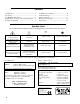
Contents Introduction .......................................................... AC Power ............................................................. The Modular Rear Panel ..................................... Amplification, Limiting, and Cooling System .... Example Application ........................................... 3 4 5 6 7 Verifying Driver Polarity .................................... 8 Troubleshooting ................................................ 8 Safety Summary ...........................
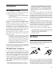
Introduction The Integrated Design The Meyer UM-P Series (UM-100P, UM-1P) selfpowered stage monitors are composed of: • one 12-inch cone driver and one 3-inch diaphragm compression driver; • phase-corrected, optimized control electronics; • a two-channel amplifier (350 Wrms/ch). The drivers, control electronics, and amplifier are integrated into a compact enclosure. The UM-P Series is intended to be used as a stage monitor but can also be used as a mid-hi and musical instrument speaker.
to compensate for hostile conditions on the AC mains: • suppresses high voltage transients up to several kilovolts • filters EMI (radio frequencies and noise present on the AC line) • sustains operation during low-voltage periods, which minimizes audio discontinuity • provides soft-start power-up, which eliminates high inrush current The UM-P can withstand continuous voltages up to 264V and allows any combination of voltage to GND (i.e. Neutral-Hot-GND, Hot-Hot-GND).
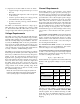
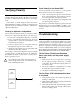
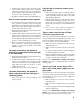
Power Connector Wiring The Modular Rear Panel Use the following AC cable wiring diagram to create international or special-purpose power connectors: brown = hot blue = neutral yellow/green = earth ground (chassis) AC cable color code If the colors referred to in the diagram don't correspond to the terminals in your plug, use the following guidelines: • Connect the blue wire to the terminal marked with an N or colored black. • Connect the brown wire to the terminal marked with an L or colored red.
Looping, Polarity, and Attenuating Audio Input Module This module has a balanced, female XLR audio input connector, a male XLR loop connector, an input polarity switch, and a level attenuator knob. With the input polarity switch in the up (+) position, pin 2 is hot relative to pin 3, resulting in a positive pressure wave when a positive signal is applied to pin 2. With the switch down (–), pin 3 is hot relative to pin 2, resulting in a negative pressure wave when a positive signal is applied to pin 2.
Power Supply Fan The power supply is cooled by a single small internal fan that turns on low when the unit is first powered up. The fan doubles its speed as the system is driven with audio. Since the fan draws air in from, and exhausts it out the side of the cabinet, there must be at least six inches on the amplifier’s side of the cabinet and adequate air flow.
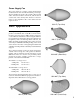
Verifying Polarity Incorrect driver polarity impairs system performance and may damage the drivers. All Meyer Sound loudspeakers are shipped with the drivers in correct alignment. If the driver or circuit wiring has been removed or disassembled it is essential to check the polarity between adjacent monitors and between drivers and between adjacent loudspeakers. Driver Polarity in the Same UM-P Use the following test procedure to verify polarity between drivers in the same loudspeaker: 1.
4. Send the audio signal to another speaker to insure signal presence and that the level is within the proper range. Turn the source level down before reconnecting the audio input and increase the level slowly to avoid a sudden blast of sound. 5. If possible, monitor the audio source with headphones. Hum or noise is produced by the speaker. 1. Disconnect the audio input. If the hum ceases, the noise originates somwhere earlier in the signal path. If the noise persists, the problem is within the UM-P.
Safety Summary English ! Français • To reduce the risk of electric shock, disconnect the loudspeaker from the AC mains before installing audio cable. Reconnect the power cord only after making all signal connections. • Pour réduire le risque d’électrocution, débrancher la prise principale de l’haut-parleur, avant d’installer le câble d’interface allant à l’audio. Ne rebrancher le bloc d’alimentation qu’après avoir effectué toutes les connections.
Rear Panel and Optional Modules The user panel and optional modules are described on page 5 of this guide. User Panel with RMS option and standard Looping Audio Input Module. Looping, Polarity, and Attenuating Input Module. High Limit LED 1 GND Circuit 1 1kΩ Each Push 25kΩ Balanced + Low Limit LED Summing Audio Input - 2 2 Push Limit 220kΩ 3 3 Case 24VFan - Earth / Chassis Inputs + Summing Inputs On / Temp.
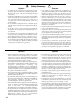
Dimensions (in inches) 22.4 22.4 16.5 16.5 UM-100P Front UM-1P Front 16.5 9.99 13.8 16.9 12.6 GND Circuit 1 1 2 3 Looping Audio Input 2 3 Push Limit 220k Ω Case 24VFan - Earth / Chassis On / Temp. Remote y set nk Service Wi 52 + Loop Re Input 0 ivit Network Act Monitor System AC Input 100-240V 50-60Hz 4A MAX ~ UM-P Top UM-P Side Contact Information Meyer Sound Laboratories, Inc.