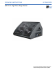
OPERATING INSTRUCTIONS ULTRAseries MJF-212A™ High-Power Stage Monitor Keep these important operating instructions. Check www.meyersound.com for updates.
Declaration of Conformity According to ISO/IEC Guide 22 and EN 45014 Operation is subject to the following two conditions: (1) this device may not cause harmful interference, and (2) this device must accept any interference received, including interference that may cause undesired operation. European Contact: Your local Meyer Sound dealer or Meyer Sound Germany, GmbH. Carl Zeiss Strasse 13, 56751 Polch, Germany. Telephone: 49.2654.9600.58 Fax: 49.2654.9600.
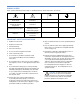
Symbols Used These symbols indicate important safety or operating features in this booklet and on the chassis: Dangerous voltages: risk of electric shock Important operating instructions Frame or chassis Protective earth ground Pour indiquer les risques résultant de tensions dangereuses Pour indequer important instructions Masse, châssis Terre de protection Zu die gefahren von gefährliche spanning zeigen Zu wichtige betriebsanweisung und unterhaltsanweisung zeigen Rahmen oder chassis Die schu
Safety Summary English - - - - - - To reduce the risk of electric shock, disconnect the loudspeaker from the AC mains before installing audio cable. Reconnect the power cord only after making all signal connections. Connect the loudspeaker to a two-pole, three-wire grounding mains receptacle. The receptacle must be connected to a fuse or circuit breaker. Connection to any other type of receptacle poses a shock hazard and may violate local electrical codes.
Contents INTRODUCTION 1 CHAPTER 1: Introducing the MJF-212A High-Power Stage Monitor 3 Advanced MJF-212A Driver Technology Integrated Amplifier and Processing Total System Approach 3 4 4 CHAPTER 2: Power Requirements 5 AC Power Distribution Looping and Cabling Power Connector Wiring Conventions Voltage Requirements Current Requirements Electrical Safety Issues 5 5 6 6 7 8 CHAPTER 3: Amplification and Audio Audio Input Amplification and Protection Circuitry MJF-212A Interconnections Cabling The
vi
INTRODUCTION INTRODUCTION These operating instructions provide important information about the form, features, function, and specifications of the MJF-212A™ high-power stage monitor. Chapter 1: Introducing MJF-212A provides a general description of MJF-212A and its capabilities and functionality. Chapter 2: Power Requirements discusses power distribution and voltage and current requirements, as well as electrical safety issues.
INTRODUCTION
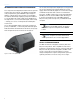
CHAPTER 1 CHAPTER 1: Introducing the MJF-212A High-Power Stage Monitor The Meyer Sound MJF-212A is a self-powered stage monitor designed to meet critical monitoring requirements in professional applications. Exhibiting flat amplitude and phase responses and exceptional impulse response, the MJF-212A meets and exceeds the capabilities of conventional stage monitors while offering the simplicity of setup and operation provided by self-powered systems.
CHAPTER 1 Integrated Amplifier and Processing As a self-powered loudspeaker, the MJF-212A incorporates a high-power, three-channel, class AB/H power amplifier using complementary power MOSFET output stages. In addition, sophisticated control circuitry is housed within the cabinet, dramatically simplifying setup and installation.
CHAPTER 2 CHAPTER 2: Power Requirements The MJF-212A monitor combines advanced self-powered loudspeaker technology with equally advanced power capabilities. Understanding the power distribution, voltage, and current requirements, as well as electrical safety issues, is critical to the safe and correct operation and deployment of the MJF-212A monitor. The MJF-212A uses a PowerCon® power connector with a loop output and complies with worldwide product safety standards.
CHAPTER 2 The blue input connector serves as the input for all the units looped in that circuit and is rated at 20 amps maximum. Please make sure never to exceed 20 amps on any single connector. Refer to Table 2.1. Table 2.
CHAPTER 2 Tip: Since the MJF-212A does not require a dedicated neutral, it can tolerate elevated voltages from ground and can be connected between line-line terminals in a 120 V 3-phase Wye system. This results in 208 V AC between lines (nominal) and will therefore draw less current for the same output power compared to operating a MJF-212A from 120 V AC (line-neutral). Make sure that the voltage remains within MJF-212A’s recommend operating window (180 V AC to 250 V AC).
CHAPTER 2 NOTE: For best performance, the AC cable voltage drop should not exceed 10 volts, or 10 percent at 115 volts and 5 percent at 230 volts. Make sure that even with the AC voltage drop, the AC voltage always stays in the operating windows. The minimum electrical service amperage required by an MJF-212A system is the sum of each loudspeaker’s maximum long-term continuous current. An additional 30 percent above the minimum amperage is recommended to prevent peak voltage drops at the service entry.
CHAPTER 3 CHAPTER 3: Amplification and Audio More than just a self-powered stage monitor, the MJF-212A uses sophisticated amplification and protection circuitry and an advanced limiting system to produce consistent and predictable results in any system design. This chapter will help you understand and harness the power of the MJF‑212A monitor’s amplifier and audio systems. Audio signals can be daisy-chained using the Loop output connector on the user panel of the MJF-212A stage monitor (Figure 3.1).
CHAPTER 3 Caution: Please note that the amplifier for the MJF-212A monitor is different from those found in other Meyer Sound loudspeakers. Specific functions for each model, such as crossover points, frequency and phase correction, and driver protection are determined by the control cards installed inside the amplifier. Do not exchange amplifiers between the MJF-212A and M’elodie or other Meyer Sound loudspeakers. high-frequency limit LED (yellow) low-frequency limit LED (yellow) Figure 3.
CHAPTER 3 The MJF-212A is performing within its acoustical specifications and operating at a normal temperature if the limit LEDs are lit for no longer than two seconds, and then go off for at least one second. If an LED remains on for longer than three seconds, that channel enters hard limiting, with the following negative consequences: Increasing input level will not increase volume. Distortion increases due to clipping and nonlinear driver operation.
CHAPTER 3 12
CHAPTER 4 CHAPTER 4: RMS Remote Monitoring System RMS is a real-time monitoring system that connects Meyer Sound self-powered loudspeakers with a Windows-based PC at the sound mix position or other location. Optional RMS software delivers extensive status and system performance data from every installed loudspeaker. The MJF-212A monitor is RMS-ready and can be upgraded by installing an RMS communication board in its user panel.
CHAPTER 4 NOTE: The Service LED indicates that the stage monitor is not commissioned on the network and has no effect on the acoustical and/or electrical activity of the MJF-212A. The monitor must be commissioned on a network using the RMS software for the service LED to stop blinking. When a loudspeaker has been installed on the network, the Service LED will be unlit and the Activity LED will flash continuously.
APPENDIX A Appendix A: Optional VEAM Multipin Connector The MJF-212A monitor requires a grounded outlet. It is very important that the system be properly grounded in order to operate safely and properly. Figure A.1 illustrates correct wiring for the creation of power cables and distribution systems for MJF-212A stage monitors shipped from the factory with the VEAM multipin connector.
APPENDIX A 16
APPENDIX B Appendix B: MJF-212A Specifications and Dimensional Drawings ACOUSTICAL Note: Recommended maximum operating frequency range. Response depends on loading conditions and room acoustics. Operating frequency range 55 Hz – 18 kHz Note: Recommended maximum operating frequency range. Response depends on loading conditions and room acoustics. Frequency response 60 Hz – 16 kHz ±4 dB Note: Half-space loading measured with 1/3-octave frequency resolution at 4 meters.
APPENDIX B AUDIO INPUT Type Differential, electronically balanced Max.
APPENDIX B PHYSICAL Enclosure Premium birch plywood Finish Black textured Protective grille Powder-coated, hex-stamped steel, black mesh Dimensions 27.07" w x 16.11" h x 23.00" d (688 mm x 409 mm x 584 mm) Weight 108 lbs (49 kg) 27.07 [688mm] 40¡ 16.11 [409mm] 8.80 [223mm] 40¡ 13.70 [348mm] 23.
APPENDIX B 20
Meyer Sound Laboratories Inc. 2832 San Pablo Avenue Berkeley, CA 94702 www.meyersound.com T: +1 510 486.1166 F: +1 510 486.8356 ©2007 Meyer Sound Laboratories Inc. 05.157.005.