
User guide


External Control Basics
Message Format 7
Hardware Interface 9
The Matrix3™ audio show control system can be controlled by external devices by sending specially formatted MIDI
messages. This chapter describes the basic structure of these messages.
Message Format
All messages to the Matrix3 hardware, regardless of the type of serial port used, utilize the MIDI System Exclusive
Protocol.
Other automation information can be found in Controlling Automation (p. 11).
All messages use the following format:
F0 (start message)
1F (LCS Audio manufacturer ID)
7E (LD-88 / LX-300 Product ID)
SUBSYSTEM (7 bit)
Frame ID (7 bit)
[Message Data] (7 bit)
CHECKSUM (7-bit)
F7 (end message)
All data bytes in the middle must be 7-bit values. The maximum size allowed for an entire single message is 512
bytes.
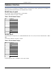
Subsystem Number
The SUBSYSTEM number is the ID code of the subsystem in the firmware. Examples of subsystems include:
00: SYSTEM CONTROL subsystem
01: XFER subsystem
03: RIF subsystem
10: to 1F CASL
10: MIXER subsystem
11: CUE LIST subsystem
14: sxCASLTimeSubsystem
21 - 22: ExcRec
25: External Control subsystem
36: Test subsystem
7f: Subsystem Manager
Frame ID
The Frame ID value should normally be 3F (Broadcast with checksum) for serial connections. Frame ID 7F (Broadcast
with no checksum) is used for TCP/IP. These ID settings broadcast a message to ALL LX-300s. For special commands
needing to be executed by only a single LX-300, you enter in the specific Frame ID instead. A value of 00 (hex)
corresponds to Frame ID 01.
Matrix3 systems can have up to 32 processors. For Matrix3 systems, the id range 39 (hex) to 7e (hex) is reserved
for a future development.
7