USER GUIDE Hardware Reference Matrix3 Audio Show Control System Edition: 2007-09-18 for CueStation 4.6.
Meyer Sound Laboratories Inc 2832 San Pablo Avenue Berkeley, CA 94702 www.meyersound.com T: +1 510 486.1166 F: +1 510 486.8356 © 2007 Meyer Sound Laboratories Inc.
© 2007 Meyer Sound. All rights reserved. Hardware Reference The contents of this manual are furnished for informational purposes only, are subject to change without notice, and should not be construed as a commitment by Meyer Sound Laboratories Inc. Meyer Sound assumes no responsibility or liability for any errors or inaccuracies that may appear in this manual.
Table of Contents LX-300 Start Up Routine 7 Overview A. Power-On Self Test B. Hardware Initialization C.
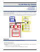
LX-300 Start Up Routine Overview A. Power-On Self Test B. Hardware Initialization C. System Firmware Startup EtherTracks Startup 7 8 8 9 10 The LX-300 contains a digital signal processor and built-in software. When you power-on ("boot") an LX-300, this software is automatically loaded. During the boot, it performs a number of diagnostic tests, initializes the hardware, and loads the latest control software.
A. Power-On Self Test For all other Frame IDs, the DSP performs special functions as described in Special DSP ID Codes (p. 16). These steps are described in detail in the sections that follow. A. Power-On Self Test During the first stage of power-on boot, the LX-DSP processor module waits for the LX-300 power and bus signal conditions to stabilize. It then tests its main SDRAM memory circuits and loads the next stage of boot software. 1. Power is turned on. 2.
C. System Firmware Startup • • • • Display "INIT" briefly on the Frame Status. Display all front panel lights for one second. Display "E1V6" on the Frame Status. The two digits correspond to the EPROM software version number. Show the Frame ID in the Frame ID display. This is a two-digit number corresponding to the Frame ID value set on the LX-DSP module. • Show the appropriate Expansion LEDs, indicating the expansion slots which have modules installed in them.
EtherTracks Startup 4. Await EPROM upload. Refer to the "Matrix3 Repair Procedures" section for more information. Subsystem Initialization Failure Subsystem initialization failure will usually result in a general system failure. The system will display an error message (see LX-300 Error Codes (p. 43)) and "REBO", and flash the Watchdog LED red and green. Subsystem failure usually indicates a failure in the LX-DSP or LX-LNK modules. Some subsystems can fail without causing a system failure.
Firmware Updates Before You Begin Firmware Update Procedures Special DSP ID Codes 11 12 16 The LX-DSP, LX-ELC, LX-VRA, and LX-EXP modules load operating system files into RAM during power-on. These files are stored in flash memory on each of the modules. Because these files are stored in the module, they are referred to as “firmware”. The version number for the firmware files and CueStation must match. If you upgrade to a new version of CueStation, you must also upgrade all firmware files.
Firmware Update Procedures loading the file again. If you use the Erase Flash command for the EtherTracks module and then switch off the LX300 (or power fails), You will have to use VirtualLX and a serial connection to an LX-COS module to recover. If part of the erase procedure had already been started, the flash memory could be corrupted or incomplete and the LX-300 will not start up properly. To remedy this situation you must force an erase of the problem firmware file using the LX-DSP module ID switch.
Firmware Update Procedures After you click OK, a blank configuration will be sent to the hardware. This is to prevent audio processing while firmware is uploaded. Another dialog box will appear, allowing you to locate the firmware file(s). All modules should be using the same firmware version as CueStation. There are five firmware files in each release: lx300_vx_x_x_xx.csf (where "x_x_x_xx" is the version number) The lx300___.csf file has two firmware files for the LX-DSP module. et_boot_v_x_x_x_xx.
Firmware Update Procedures This assumes that the firmware in the LX-DSP and LX-ELC has been completely erased. You must have an LXCOS Communication / Synchronization module in your system since the EPROM in the LX-DSP module is only able to connect to a serial port. Important If there is an LX-EXP module in the system with an ID set higher than 32, it will not accept firmware while in EPROM mode. Change the ID to a number less than 32 before beginning the firmware upload.
Firmware Update Procedures 4. In the drop-down menu, select Use TCP Connection. An alert box will open with a "System Reset Warning". This is a normal caution. Click Yes. 5. In CueStation 4 open the Mixer Configuration window. Select Configuration > Upload Firmware. Make sure that you comply with the instruction in the alert box that opens and then click OK. 6. A file requester window will open. Navigate to the location with the CS4 firmware files.
Special DSP ID Codes Special DSP ID Codes The ID switch on an LX-DSP module may be used to force the LX-300 to erase flash memory areas in the DSP, EXP, and ELC modules. You may need to do this if flash memory has become corrupted, or if there is a problem after uploading system flash. Both situations are rare, and erasing flash memory is not required in normal operation.
Special DSP ID Codes Erasing Flash Memory Caution If you erase the LX-ELC flash, you must upload replacement firmware files to the LX-ELC module before it will work again. You will need an LX-COS module for serial connection or a network connection to an LX-ELC module on another LX-300 in the system that has not been erased. In CueStation 4 you will have to use VirtualLX in order to connect to a LX-300 with an erased ELC module.
Matrix3 Repair Procedures Overview Replacement of Power Fuse Removal and Installation of Modules 19 19 20 Physical repair of the Matrix3 system is limited to replacement of expansion modules. Overview Skills Required • Removal of LX-300 from audio system. • Removal and installation of expansion modules. • Return of LX-300 to system, including cable re-connection. Required Tools and Components • Anti-static equipment, including a personal grounding strap. • #2 Phillips screwdriver.
Removal and Installation of Modules Removal and Installation of Modules All modules must be installed to a valid slot position. Incorrect assignment of modules to slots may result in hardware failure or poor performance, although the modules themselves will not be damaged. Caution Circuit card assemblies contain Electrostatic Discharge Sensitive (ESDS) components. Take appropriate precautions when handling expansion modules. Module Removal 1. Power off the LX-300. 2.
Removal and Installation of Modules 8. Power on the LX-300, and observe the System LED and Frame Status displays. A detailed description of the boot process is provided in the LX-300 Start Up Routine (p. 7). 9. Within four seconds of power-on, the System LED must display and remain solid green (except after the first all-indicators-on test, when it will momentarily flicker red). Wait for the LX-300 to finish booting.
LX-300 Maintenance Overview Recommended Schedule Inspection and Maintenance Procedure Operational Testing 23 23 23 24 Dust, heat, humidity and power surges are the most significant dangers to the system and its components. For best performance, the Matrix3 should be operated in a cool, low-dust, low-humidity environment. In most operating environments, periodic inspection of the LX-300 will ensure its longevity.
Operational Testing Important Tighten the left-hand captive machine screws on double-width modules first, to prevent warping the panel. The chassis will be secured to its rack using four captive machine screws, located at either edge of the front panel. There may be optional mounting points at the rear of the LX-300. Tighten these as appropriate. Do not over-tighten. 4. You may choose to clean the front panel of LX-300s using ordinary glass cleaner. Dampen the cloth and wipe.
Hardware Specifications LX-300 Specifications Power Requirements Component Specifications 25 26 27 This chapter presents detailed electrical, mechanical and physical specifications for the Matrix3 and its modules. LX-300 Specifications This illustration shows a typical Matrix3 back panel. The valid slot assignments are provided below. Table 2.
Power Requirements Operating Environment 0° to 40° Celcius (32° to 100° Fahrenheit). 5% to 95% humidity, non-condensing. Low dust levels. Warning The internal temperature, as reported in the System Status window, is typically 10º C hotter than the operating environment. The Matrix3 may sustain damage if the internal temperature reaches 50º C. Storage Environment 0° to 80° C (32° to 175° F). 5% to 95% humidity, non-condensing. Power Consumption AC, 47–70Hz, 100–250V, single phase.
Component Specifications Table 3. LX-300 IEC AC Power Connector Pin Name 1 Hot 2 Ground 3 Neutral Component Specifications LX-ML8 Mic/Line Analog Audio Input The LX-ML8 provides eight balanced XLR audio inputs with software-controlled microphone and line level gain settings. The analog audio is converted to 24bit/48kHz digital data for processing by the LX-DSP. Up to two analog input cards (for a total of sixteen input channels) can be used in a single LX-300.
Component Specifications Pin-outs: LX-ML8 Balanced Female XLR Pin Name Use 1 GND Shield 2 Signal+ +Analog balanced input 3 Signal- -Analog balanced output LX-Ai8 Analog Audio Input Provides eight balanced-XLR analog audio signal inputs. Performs 24bit/48kHz digital conversion with three conversion scaling settings. Channels Eight analog inputs. Frequency Response 20Hz —20kHz. Sampling 24bit/48kHz. Dynamic Range 98dB. S/N Ratio -74dB. THD <0.
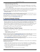
Component Specifications ADA Scale: Inputs A to D Scale Settings CueStation INPUTS window 20050929 Digital Signal Level Input Scale Setting Input Signal dBu +6 +16 +26 +6 dBu = 1.55 Vrms 2.2 V p-p 0 dBfs +16 dBu = 4.9 Vrms 6.9 V p-p CLIP 0 dBfs -10 dBfs +26 dBu = 15.5 Vrms 21.9 V p-p CLIP CLIP 0 dBfs -10 dBfs -20 dBfs 0dBu=.775Vrms +4dBu=1.
Component Specifications LX-Ao8 Analog Audio Output Provides eight balanced-XLR analog audio signal outputs. Performs 24bit/48kHz digital conversion with three conversion scaling settings. Channels Eight analog outputs. Frequency Response 20Hz —20kHz. Sampling 24bit/48kHz. Dynamic Range 98dB. S/N Ratio -74dB. THD <0.
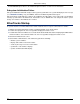
Component Specifications ADA Scale: Outputs D to A Scale Setting CueStation OUTPUTS window 20050929 Analog Output Signal Level Output Scale Setting +6 +16 +26 Digital Signal Level 0 dBfs + 6 dBu +16 dBu +26 dBu - 2 dBfs + 4 dBu +14 dBu +24 dBu -10 dBu - 0 dBu +10 dBu -16 dBfs +6 dBu 1.55 Vrms +16 dBu 4.9 Vrms +26 dBu 15.
Component Specifications LX-CBR CobraNet Audio Interface Provides CobraNet 20bit/48kHz digital audio data transmission over Ethernet networks. Pin-out CobraNet communications: Use standard CAT5 cabling. LED Status Indicator Link Watchdog Conductor Fault RX Data RX Error TX Data TX Error Green LED indicates normal operation. Red LED indicates a fault or error condition.
Component Specifications LX-AES 33
Component Specifications 34
Component Specifications LX-DSP System Processor Performs matrix mixing automation and control, using the TI-TMS320C6701 Digital Signal Processor. This DSP card also holds 32MB SDRAM and 8MB Flash memory, allowing stand-alone operation once programmed with an automation cue list. The DSP is also interfaced to four relay contact outputs, four digital sensor inputs and two analogue sensor inputs for control and reading of external devices.
Component Specifications LX-EXP Expansion DSP The expansion DSP card provides additional processing power for the LX-300. LX-VRA VRAS DSP The VRAS DSP provides reverberation, and early and late reflections capabilities for the Matrix3.
Component Specifications LX-ELC Ethernet/Wild Tracks Provides Ethernet communications link between external hardware and the Matrix3 system. Also provides a SCSI hard drive interface for use with Wild Tracks playback. Ethernet connection is IEEE 802.3 and is 100 base T. Wiring must conform to EIA.TIA 568 standard with CAT-5 or better cable. Each LX-ELC module that is used for Wild Tracks requires a network connection to transfer audio files.
Component Specifications LX-LNK Interconnect Provides a high-speed connection between LX-300s. Carries command data and 32bit/48kHz digital audio data. An optional optical transceiver module extends the maximum transmission range. Use only Link cables from Meyer Sound. These are Fibre Channel cables that have been qualified for high speed data use. They have a yellow label at each end that is marked "LX-Link". Systems must be connected in a ring.
Component Specifications 39
Component Specifications LX-COS Comm/Sync Provides a communications link to the CueStation host computer system (or the computer hosting your custom control software), a SMPTE Time Code signal generator and receiver, and MIDI I/O. Ports RS232 serial, RS422 serial, MIDI In/Out, XLR SMPTE In/Out Pin-outs Table 4.
Component Specifications Table 7. Five-pin DIN Female MIDI Out Pin Name Use GND Shield 4 +5V Reference current 5 Data Send data 1 2 3 Table 8. XLR Female SMPTE In Pin Name Use 1 GND Shield 2 +data +Balanced analog input 3 -data -Balanced analog input Table 9.
LX-300 Error Codes Status LED Blink Codes Frame Status Error Codes Frame Status Error Messages CueStation Log Window Messages 43 43 44 45 The LX-300 reports the identifiable errors through one or a combination of methods: Status LED blinking, Frame Status error code reports, Frame Status error messages, and CueStation Log window messages. Identifying the error and its probable root cause helps you choose an appropriate troubleshooting strategy.
Frame Status Error Messages Error Code Explanation IE14 Could not load Flash program IE16 Could not start BoxNet IE17 Could not start SerialNet IE18 Could not obtain TCP/IP Hostname IE19 Could not obtain Midi serial socket IE20 Could not start Midi Parser IE21 Could not start Midi Subsystem Manager IE22 Could not start Subsystem IE23 Could not start Midi Xfer system IE24 Could not start CASL subsystem IE25 Could not start Externals subsystem IE26 Could not erase System Flash IE27
CueStation Log Window Messages Repeated occurrence of an error indicates a fault with the associated expansion module ("DMA0" corresponds to an Analog Audio Input module; "DMA1" to a CobraNet module). CueStation Log Window Messages CueStation's Log window reports a number of errors from the Matrix3 system. These can be helpful in diagnosing the root cause of a failure. The messages relevant to booting an LX-300 are: Error Code M3 E1.5.
Appendix Returns Policy Shipping Address 47 47 Returns Policy Please contact one of our product specialists: Tel: +1 (626) 836-0446 Fax: +1 (626) 836-4883 http://LCSforums.com support@meyersound.com Shipping Address Product returns *must* be packaged appropriately. Shipment without adequate shock protection and electrostatic discharge protection may void your product warranty. Level Control Systems can not assume responsibility for damage caused during shipping.