QUICKFLY RIGGING MANUAL M3D™ and M3D-Sub M SERIES
DECLARATION OF CONFORMITY ACCORDING TO ISO/IEC GUIDE 22 AND EN 45014 The manufacturer: Meyer Sound Laboratories Inc.
SYMBOLS USED These symbols indicate important safety or operating features in this booklet and on the chassis.
SAFETY STATEMENT PLEASE READ THIS SECTION CAREFULLY AND IN ITS ENTIRETY. IT CONTAINS CRITICAL INFORMATION REGARDING SAFETY ISSUES, INCLUDING GUIDELINES FOR GENERAL SAFE USE OF RIGGING SYSTEMS AS WELL AS ADVISORIES ON GOVERNMENT REGULATIONS AND LIABILITY LAWS. MEYER SOUND CANNOT BE HELD RESPONSIBLE FOR CONSEQUENCES THAT MAY ENSUE DUE TO FAILURE TO READ AND COMPLY WITH INFORMATION IN THIS SECTION.
Advisory Note: Safety Responsibilities “Above the Hook” In most touring applications of rigging systems, the touring sound provider is normally responsible for ensuring the safety of the suspension system only below the attachment point. The safety and suitability of the attachment point is generally seen as the responsibility of the venue owner or operator. However, this distinction (“above the hook” versus “below the hook”) can be open to interpretation.
viii
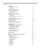
CONTENTS Introduction Assembling Blocks for Transport Truck Pack M3D Transport Before Hanging an M3D Array 1 1 1 3 3 Choosing Rigging Point Capacities M3D Placement Calculator Measuring a Venue 3 4 5 General Hanging Considerations 6 Do’s and Don’ts Lifting Mechanisms Use Front and Back Motors Whenever Possible Choosing Pickup Points Array Assembly and Angle Adjustment Starting Array Assembly Stacking an M3D Array Attaching Motors to the MTG-3D Top Grid Attaching M3Ds to the MTG-3D Top Grid Adjust
Appendix B — Physical Specifications 32 M3D Physical Specifications M3D-Sub Physical Specifications MTG-3D Top Grid Physical Specifications 32 33 33 Appendix C — MTF-3D Transition Frame Assembly Procedure 35 MTF-3D Transition Frame Attaching Loudspeakers to Transition Frame Attaching the Adjustable Link Assembly to the MRF-3D Rigging Frames Rear Front 35 35 36 36 37 Glossary x 38
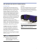
M3D AND M3D-SUB QUICKFLY RIGGING MANUAL INTRODUCTION Truck Pack The M3D and M3D-Sub QuickFly rigging system is a complete integrated solution for transporting and flying M3D and M3D-Sub loudspeakers. This system includes everything below the motors, to the caster rails and covers that carry and protect the system in transport. All the hardware for rigging the system remains captive to the loudspeakers and MTG-3D Top Grid.
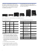
Using a three- or four-high M3D block will make each block heavier (see Table 1) and less stable, so the blocks will require extra care when rolling over an uneven surface and up truck ramps. Conversely, larger blocks will make more efficient use of a truck’s cargo space and make a more efficient load-in and strike.
TIP: Meyer Sound’s optional transit covers will protect M3Ds stacked for transport. They are easy to use, because one side opens with Velcro seams, allowing two stagehands to easily put on the cover without having to lift it over the top of the block. We suggest you strap each block, once loaded, with a cargo strap to prevent rubbing through the covers and damaging the M3D cabinets or adjacent equipment. M3D Transport As a reference, a three-high M3D block weighs approximately 1245 pounds (564.
When choosing your rigging point capacities, always keep in mind that the entire weight of the array may shift completely to either the front or back points. Three factors contribute to variations in the center of gravity: the venue, as shown in Figure 4, can display up to three balconies. The Meyer Sound M3D Placement Calculator is approved by a certified structural engineering firm. 1.
MEASURING A VENUE You are required to enter the venue’s dimensions into the M3D Placement Calculator. Another less accurate option is to measure the venue by pacing it off, using a pedometer similar to item 3 in Figure 5, and using this measurement to make an educated estimate. If scaled sectional drawings of the venue are available, you can use the dimensions from these drawings to determine the M3D array setup.
Once you enter measurements into the M3D Placement Calculator, it will help you visualize the approximate vertical splay angles needed. The calculator will also help with other rigging considerations. Save the results of these calculations for use when you assemble the M3D array as described in the section “Array Assembly and Angle Adjustment.
LIFTING MECHANISMS The number and lift capacity of chain motors used to lift the array are dependent on the array’s combined weight, including the weight of any underhung clusters, and its orientation and splay. For a smaller array, it may be sufficient to use 1-ton motors, but for larger arrays, 2-ton motors may be necessary. The lift capacity of any single motor or set (in a fourhoist configuration) of motors must be sized to support the entire weight of the array, including cable.
NOTE: When using chains or making custom bridle lengths to achieve vertical tilt, be sure the center of gravity of the final hung array is within the allowable limits of the MTG-3D Top Grid. (See “M3D Placement Calculator.”). 3. The array may develop as much as 3 feet of downstage (front) curve (see Figure 8) while being assembled. Often, the array will be assembled near the downstage edge or a similar situation.
TIP: If the bottom of the array ends up being too far downstage during assembly, have stagehands breast it upstage until assembly is complete and it is flown to its final trim position. 5. It is often necessary to increase the stability of an array in venues with very high structural steel from which the array is suspended. The rigging points can be located a small distance, that is, 6 inches (152.4 mm) diagonally, from the MTG-3D Top Grid dimensions for a four-motor configuration.
STACKING AN M3D ARRAY ATTACHING MOTORS TO THE MTG-3D TOP GRID Use rated steel cables and shackles when attaching motors to the MTG-3D Top Grid, as shown in Figure 12. The MTG-3D Top Grid will accommodate 5/8-inch and 3/4-inch shackle sizes on its pickup points. Figure 10. Checking phase (chain direction) 4. Run the chain through the motors until they are approximately 2 feet off the ground. 5. Attach the chain bags and feed the unused chain into the bag. 6.
The allowable system center of gravity range must be within the front rigging point and one of the pickup choices provided, as illustrated in Figure 34 on page 26. BRP 1 from the main frame 1. Once the motors are attached to the MTG-3D Top Grid, raise the MTG-3D Top Grid, as shown in Figure 13, to the necessary working height in preparation for attaching the first block of M3Ds. Adjust the MTG-3D Top Grid to be parallel with the top M3D of the block.
ADJUSTING ANGLES By using both MAPP Online and the M3D Placement Calculator, you should now have determined the required tilt for the MTG-3D Top Grid and splay angles between elements for your array. The M3D Placement Calculator (see “M3D Placement Calculator”) also provides a warning indication if the center of gravity falls too close to, or outside of, the front or back point that was chosen in the array’s final configuration.
Adjusting MTG-3D Top Grid Uptilt With the MTG-3D Top Grid’s rear link in the extended position (as shown in Figure 17 and Figure 18), the front CamLink can be adjusted to provide between 1˚ and 5˚ of uptilt. The MTG-3D Top Grid’s rear link works in combination with its front CamLink to produce the desired angle of uptilt. +1˚ to +5˚ Figure 18 shows the MTG-3D Top Grid with the rear link extended. Note the direction of tilt with this configuration. Figure 18.
3. Bump the motors as needed to relieve sheer stress on the QRPs in order to free them from the holes. 4. Bump the motors to pull the cabinet further upward until the desired CamLink hole is correctly aligned. ! CAUTION: Do not hold the CamLink by placing your fingers between the cabinets. 5. Check the hole alignment by moving the CamLink from the side of the cabinet as it swings through the rigging frames. Figure 19. Removing the QRP from the MTG-3D Top Grid’s front CamLink 2.
Figure 21. Adjusting angle using the alignment block ! CAUTION: When the QRPs are removed from the CamLinks, take care when adjusting the motor hoists. If the motors are raised too high with only the rear link’s QRPs installed, the lower loudspeaker block can swing under the upper block of flown loudspeakers. Always use small motor bumps when rigging the system while in this state. Figure 22.
3. Move the CamLink to the 0˚ position and secure with a QRP as shown in Figure 24. 4. While the upper array is still floating, visually align the cabinets to be sure the CamLinks will not bind into the mating end frame. 5. Once the rear link is sitting inside the end frame, move the QRP into the end frame’s hole, awaiting alignment with the rear link as shown in Figure 26. TIP: Use small motor bumps (small movements up or down) as the alignment gets closer.
10. Use up or down motor bumps to pivot (or hinge) the lower block to the upper cabinets, allowing you to set the QRP into the desired CamLink hole as shown in Figure 28 and secure it as shown in Figure 29. Figure 27. Rear link QRP inserted TIP: Here is another technique for setting the rear link. Position the upper array approximately 1 inch (25 mm) above the waiting cabinet block. Push the flown array behind the lower block approximately 2 inches (50 mm).
FLYING A COMPLETED ARRAY Figure 31 shows an example of rigging points chalked on the ground, a fully rigged block of three M3D loudspeakers with an MTG-3D Top Grid mounted, positioned, and ready to fly. 5. After the M3D array has been flown into its final vertical position, check the horizontal angle of the array.
INCLUDING M3D-SUBS IN AN ARRAY M3D-Subs can be included in an array in the same manner as M3Ds. Refer to the M3D Operating Instructions for details on the use of M3D-Subs in an array and suggestions for the optimum configuration with M3D loudspeakers to achieve the desired coverage and sound pressure level (SPL) for a venue while maintaining maximum headroom for all elements of the array. The M3D-Subs may be stacked up to four high for transport and use.
APPENDIX A — CONFIGURATIONS AND LOAD RATINGS GENERAL MEASURED ANGLES This appendix contains various hanging configurations for M3D loudspeakers using an MTG-3D Top Grid. This appendix also contains allowable configurations of bridle attachments, bridle lengths, attachment points on the MTG-3D Top Grid, the maximum weight, and maximum number of M3D loudspeakers for each configuration. Two angles are used in the following tables.
CONFIGURATION A the attachment points on the MTG-3D Top Grid is 52.50 inches (1334 mm). Figure 34 illustrates the hanging configurations that are considered in the calculations listed in Table 3 and Table 4. In these configurations, the distance between Back Rigging Point (BRP) 1 BRP 2 BRP 3 Figure 34. Bridles in front-to-back configuration with the rear extension frame either retracted or extended Table 3.
Table 4. Minimum Allowable Bridle Leg Lengths with Varying Number of M3D Loudspeakers 5:1 Safety Factor Maximum Number of M3Ds Maximum Angle Between Bridle and Grid α (deg) Minimum Allowable Bridle Leg Lengths Maximum Angle Between Bridle and Grid α (deg) Minimum Allowable Bridle Leg Lengths 1 43˚ 3.00 ft. (910 mm) 47˚ 3.25 ft. (990 mm) 2 43˚ 3.00 ft. (910 mm) 47˚ 3.25 ft. (990 mm) 3 43˚ 3.00 ft. (910 mm) 47˚ 3.25 ft. (990 mm) 4 43˚ 3.00 ft. (910 mm) 47˚ 3.25 ft.
CONFIGURATION B Use Table 5 and Table 6 when the lifting configuration uses bridle legs spanning the short sides of the M3D as shown in Figure 35. Figure 35. Using bridle leg short side pickup points (BRP 1) Table 5: Suspended Weight and Quantity of M3D Loudspeakers with Varying Bridle Leg Lengths Bridle Leg Lengths Angle Between Bridle and Grid α (deg) 5:1 Safety Factor 7:1 Safety Factor Max Top Grid Angle Maximum Allowable Suspended Weight Maximum Allowable Qty.
Table 6. Minimum Allowable Bridle Leg Lengths with Varying Number of M3D Loudspeakers 5:1 Safety Factor Qty. of M3Ds Angle Between Bridle and Grid α (deg) Minimum Allowable Bridle Leg Lengths Angle Between Bridle and Grid α (deg) Minimum Allowable Bridle Leg Lengths 1 51˚ 2.00 ft. (610 mm) 51˚ 2.00 ft. (610 mm) 2 51˚ 2.00 ft. (610 mm) 51˚ 2.00 ft. (610 mm) 3 51˚ 2.00 ft. (610 mm) 51˚ 2.00 ft. (610 mm) 4 51˚ 2.00 ft. (610 mm) 51˚ 2.00 ft. (610 mm) 5 51˚ 2.00 ft. (610 mm) 51˚ 2.
CONFIGURATION C Use Table 7 and Table 8 when the bridle legs are parallel to the side of the M3D and when the rear pickup points are on the closed MTG-3D Top Grid extension as shown in Figure 36. Figure 36. Using bridle leg short side pickup points (BRP 2) Table 7.
Table 8. Minimum Allowable Bridle Leg Lengths with Varying Number of M3D Loudspeakers 5:1 Safety Factor Qty. of M3Ds Angle Between Bridle and Grid ∝ (deg) Minimum Allowable Bridle Leg Lengths Angle Between Bridle and Grid ∝ (deg) Minimum Allowable Bridle Leg Lengths 2 43˚ 2.25 ft. (690 mm) 47˚ 2.25 ft. (690 mm) 3 43˚ 2.25 ft. (690 mm) 47˚ 2.25 ft. (690 mm) 4 43˚ 2.25 ft. (690 mm) 47˚ 2.25 ft. (690 mm) 5 43˚ 2.25 ft. (690 mm) 52˚ 2.50 ft. (760 m) 6 47˚ 2.25 ft. (690 mm) 56˚ 2.
CONFIGURATION D When using bridle legs spanning the short side of the M3D (front to back) with the pickup attached to the extended MTG-3D Top Grid pickup points as shown in Figure 37, use Table 9 and Table 10 to determine the maximum number of M3Ds and the allowed bridle leg lengths required to conform to the appropriate safety factor for the venue. Figure 37. Bridle legs using attachment points on an extended MTG-3D Top Grid (BRP 3) Table 9.
Table 10. Minimum Allowable Bridle Leg Lengths with Varying Number of M3D Loudspeakers 5:1 Safety Factor 28 7:1 Safety Factor Qty. of M3Ds Angle Between Bridle and Grid ∝ (deg) Minimum Allowable Bridle Leg Lengths Angle Between Bridle and Grid ∝ (deg) Minimum Allowable Bridle Leg Lengths 1 43˚ 3.25 ft. (990 mm) 47° 3.50 ft (1070 mm) 2 43˚ 3.25 ft. (990 mm) 47˚ 3.50 ft. (1070 mm) 3 43˚ 3.25 ft. (990 mm) 47˚ 3.50 ft. (1070 mm) 4 43˚ 3.25 ft. (990 mm) 47˚ 3.50 ft.
CONFIGURATION E The pickup configuration using the center pickup points on the MTG-3D is shown in Figure 38. ! CAUTION: The MTG-3D Top Grid must not rotate (tilt) more than 12 degrees from horizontal. Figure 38. Using center pickup points Table 11. Suspended Weight and Quantity of M3D Loudspeakers Bridle Leg Lengths Angle Between Bridle and Grid α (deg) 5:1 Safety Factor 7:1 Safety Factor Max Top Grid Angle Maximum Allowable Suspended Weight Maximum Allowable Qty.
CONFIGURATION F Each motor hook may be attached to the corner of the MTG-3D Top Grid with two 5/8-inch or 3/4-inch shackles. There is a maximum combination of 16 M3D and M3DSub or other loudspeakers, such as MSL4s and CQs, which can be underhung in this configuration. The total weight of the hung system cannot exceed the total equivalent weight of 16 M3Ds.
CONFIGURATION G In configuration G, the steel cables are connected to a single lift point from the four rigging points on the MTG-3D Top Grid. The array is lifted from a single point attached to each of the MTG-3D Top Grid corner lifting points as shown in Figure 40. An array of up to 16 M3Ds can be supported. NOTE: The lift mechanism must be rated to support the total weight of the entire array. The array must have suitable tie-downs to eliminate sway and twist.
APPENDIX B — PHYSICAL SPECIFICATIONS M3D PHYSICAL SPECIFICATIONS Enclosure Multi-ply hardwood Finish Black textured (weather protected) Note: Custom color available upon request Protective grill Powder-coated hex stamped steel Rigging QuickFly MRF-3D Rigging Frame with integral CamLinks, rear connecting bars, and captive quick release pins Weather protection Standard Dimensions 54" W x 20" H x 30.5" D (1372 mm x 508 mm x 775 mm) Weight Net: 415 lbs (188 kg) 20.00" [508 mm] 10.00" [254 mm] 9.
M3D-SUB PHYSICAL SPECIFICATIONS Enclosure Multi-ply hardwood Finish Black textured (weather protected) Note: Custom color available upon request Protective grill Powder-coated hex stamped steel Rigging QuickFly MRF-3D Rigging Frame with integral CamLinks, rear connecting bars, and captive quick release pins Weather protection Standard Dimensions 54" W x 20" H x 30.5" D (1372 mm x 508 mm x 775 mm) Weight Net: 395 lbs (179 kg) 20.00" [508 mm] 10.00" [254 mm] 9.
Figure 43.
APPENDIX C — MTF-3D TRANSITION FRAME ASSEMBLY PROCEDURE Use the following procedure when transitioning in an array from M3Ds to Meyer Sound MSL-4s or CQs (see Figure 44). 4. The adjustable link rear link assemblies include a short link plate, hammer-lok, and chain. 5. The 2.5-inch QRPs are used for holding the chain to the transition frame. 6. Oval handle hitch pins are used for holding the loudspeakers to the transition frame. 7. The lynch pins are used with the oval handle hitch pins.
ATTACHING THE ADJUSTABLE LINK ASSEMBLY TO THE MRF-3D RIGGING FRAMES TIP: When you are lowering the front arm on to the rings, it is easiest to do so from one side — gradually lowering it to the other side as the rings each fit into the corresponding holes in the arm. Once the first ring is positioned into the first slot, insert the hitch pin to anchor the front arm. This will simplify the insertion of the other five hitch pins.
Front 1. Raise the M3D array to give sufficient space to slide the front (long) adjustable link plate up (vertically) in between the MRF-3D Rigging Frame and the CamLink, and use the same hole that is used to adjust the CamLink (see Figure 46). 2. Remove the QRP holding the CamLink in place. The CamLink should swing down freely. 3. Slide the adjustable link plate up between the CamLink and MRF-3D, aligning the weldment hole with the appropriate hole in the adjustable link plate.
GLOSSARY A array A group of flown loudspeakers that has been configured to produce optimum sound pressure level (SPL) and coverage in a particular venue. B block A group of loudspeakers from an array that has been broken down into convenient-sized groups for transport. bridle A method of using two steel cables connected to two lifting points on an array’s top grid, brought together to a common point and attached to a lifting motor. bridle leg BRP One side of a bridle. Back rigging point.
O out Rigging term denoting hardware moving in an upward direction. P pullback or pullback motor Rigging term used to describe the process of attaching rope, a sling, or a pullback motor to the bottom rear of an array to achieve further downtilt than is available using the array’s center of gravity alone. Q QRP Quick Release Pin, 0.5" x 2." (13 mm x 64 mm), used in all M3D rigging points. R rigging point Sometimes referred to as a lift point.
Meyer Sound Laboratories Inc. 2832 San Pablo Avenue Berkeley, CA 94702 USA T: +1 510 486.1166 F: +1 510 486.8356 techsupport@meyersound.com www.meyersound.com © 2003 Meyer Sound Laboratories Inc. All Rights Reserved 05.105.400.01 Rev.