USER GUIDE CueMixer Matrix3 Audio Show Control System Edition: 2007-09-19 for CueStation 4.6.
Meyer Sound Laboratories Inc 2832 San Pablo Avenue Berkeley, CA 94702 www.meyersound.com T: +1 510 486.1166 F: +1 510 486.8356 © 2007 Meyer Sound Laboratories Inc.
© 2007 Meyer Sound. All rights reserved. CueMixer User Guide The contents of this manual are furnished for informational purposes only, are subject to change without notice, and should not be construed as a commitment by Meyer Sound Laboratories Inc. Meyer Sound assumes no responsibility or liability for any errors or inaccuracies that may appear in this manual.
Table of Contents CueMixer™ Setup 7 Connecting the CueMixer CueMixer Controls 11 Modes Page Select Transport Buttons EQ Isolate Mute User Buttons Programming CueMixer Functions 15 CueMixer Setup User A Mode Using the CueMixer 21 Mixing with Virtual Groups Executing Cues with User A Buttons CueMixer Details 23 Basic Operation Reference Service and Troubleshooting 29 Service Calibration 5
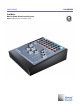
CueMixer Setup Connecting the CueMixer 7 The CueMixer™ is a physical control surface for the Matrix3™ audio show control system. The faders and buttons provide a flexible interface for controlling audio processing and automation within the Matrix3. Connecting the CueMixer Power is suppled to the MS-CUEMIXER from an external +12VDC/2.5A power supply (included.
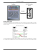
Connecting the CueMixer CueMixer LX-COS module Port B RS-422 RS-422 Serial Cable On the Matrix3 LX-COS module, Port A and Port B use the same connector pin-outs as the CueMixer, so the cable connections are swapped from end to end. The cable needed to connect the LX-COS module to the CueMixer should be wired as shown. Use a two-shielded-pair stranded cable with low capacitance. Pins 4&5 are one pair, and 8&9 are the second pair.
Connecting the CueMixer Table 1. CueMixer RS-422 Connection Pin Purpose 1 Shield 4 TxD+ 5 TxD- 8 RxD+ 9 RxD- DIP Switch Settings The dip-switches on the rear panel of the CueMixer are not used and their settings ignored by the electronics.
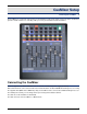
CueMixer Controls Modes Page Select Transport Buttons EQ Isolate Mute User Buttons 12 12 13 14 14 14 14 Controls on the CueMixer are organized into sections with related functions grouped together. These sections match functions in CueStation software. They are Transport, Editing, Navigation, EQ, Isolate and Mute. The two most used buttons have been placed at the top left and the top right. System Master The top left button is the System Master [0].
Modes Modes Next to each button is an LED. On the top two rows of buttons, these LEDs are used to display the current mode and page selection. There are four modes on the CueMixer. These are System Master, Trims, Shift and EQ. For each mode, there is a single button that will enter the mode - which is why there is a graphic box around both the button and the LED. Note The GO button is a special case; the LED is on all of the time to highlight the button.
Transport Buttons For example, to select faders 33 to 40, you need “page 5”. Press then release the Shift key (LED lights) then press the Isolate button for fader number 5. There are blue numbers beneath each of the LEDs on the Isolate row of buttons. These show pages 1 to 8. There are black numbers about the LEDs on the Mute row of buttons. These show pages 9 to 16.8 Table 3.
EQ that will allow automated levels to be offset. For example if you have a substitute musician and you need to adjust the overall level without changing the programmed fades, you could use the trim control. When the Trims LED is green selection of Inputs, Bus Lvls, Outputs, Aux Out, or VGroups, will set the faders to control the Trims for these controls. If the Trims LED is dark, the faders will control the Levels for these controls when selected. EQ The EQ button [9] lets you edit the EQ settings.
Programming CueMixer Functions CueMixer Setup User A Mode 15 19 CueMixer Setup By default the LX-300 connection to CueMixer is not enabled. An External Subcue is used to enable the connection to a CueMixer. When the LX-300 is first powered up, the CueMixer is not enabled. You must enable it by using the CueMixer RIF108 > Enable RIF command in the Frame Control window, or by programming an External Subcue. From CueStation you can disable controls on the CueMixer.
CueMixer Setup Enable Console Modes Enables these controls on the CueMixer. By default these are all of enabled until you use this command and select "Disable" from the drop-down menus to disable the control on the CueMixer. Enable EQ/Trim Modes Enables these controls on the CueMixer. By default, these are all of enabled until you use this command and select "Disable" from the drop-down menus to disable the control on the CueMixer.
CueMixer Setup Enable Misc Console Modes Enables these controls on the CueMixer. By default these are all of enabled until you use this command and select "Disable" from the drop-down menus to disable the control on the CueMixer. The “Editing” controls are the ones accessed by pressing Shift, and then using the Page 1, 2, 3, and 4 buttons. Assign User A/B Cues This external sets the Cue ID number to be fired when the User A or User B button is pressed.
CueMixer Setup Note Do not confuse User A button with User A mode. User A button fires a single cue when pressed. When you enter User A mode (LED next to user A button is ON), then you have the use of the bottom two rows of buttons on the CueMixer available to fire cues. (see “Set User A Mode” below.) Enable Cue 0 CueMixer Enables the CueMixer User A and User B buttons to send Cue id 0. There is not a way to set the User button to Off. It must have a cue number assigned.
User A Mode Set Port on LX-300 Port B on the LX-COS module is the default port for connecting a CueMixer, but you can change the connection to Port A. Please note that each LX-300 will only support one CueMixer. User A Mode This command is used to assign the Cues that are fired by last two rows of buttons on the CueMixer when you are in User A mode. Page There are a total of 16 pages available. Button 1 to 8 are the "Isolate" buttons left to right. 9 to 16 are the "Mute" buttons left to right.
Using the CueMixer Mixing with Virtual Groups Executing Cues with User A Buttons 21 21 Connect the CueMixer to a Matrix3 LX-COS module (Port B is the default connection), turn on the power, send a configuration to the Matrix3, and then send the CueMixer RIF-108 > Enable RIF command. You can connect one CueMixer to each Matrix3. To get you started, the following are a couple of examples from CueMixer installations.
CueMixer Details Basic Operation Reference 23 24 Basic Operation When the CueMixer is first powered up it starts with System Master as the current mode. The System Master LED in the upper left corner is lit and the first two faders are the Automated System Level and the Manual System Level. The user can press and release the SHIFT key to enter the SHIFT-mode. When in the SHIFT-mode, the LED next to the SHIFT button will be lit.
Reference Reference The following section provides details for each, LED, button and feature found on the CueMixer. First Row of LEDs The mode LEDs are used to indicate the active mode. When using the CueMixer along with a computer you will see the active mode as the top window on the computer monitor (IF you have Enabled “Window Follow” for the CueMixer). The mode indicates what the faders are controlling. System System Level (Auto) and Manual System Level (Manual) faders active.
Reference Show This causes the Status display on the front of the LX-300 to show the next cue in the active Cue List. The status display is in the form “Nxxx” When N shows that it is the “Next” cue and xxx is the cue ID number for the next cue. GO This is the same as the GO button in the transport window. Pressing it is the same as clicking on the GO button on the computer monitor. Note that the LED above this button is lit all of the time. Second Row of LEDs Shift Lights to show that Shift is toggled on.
Reference (Shifted) [c.NEW]: Cue Lists window- Makes a new cue entry with the default name, captures all, and then puts it in a cue list. A Cue List must be selected in the Cue Lists window. This is the same as pressing F4 while in the Cue Lists window with a Cue List selected. Page Select 2 (Unshifted) Hot button select of page 2. (Shifted) [c.ALL]: Cue Library window- is the Capture ALL command. A Cue must be selected in the Cue Library window.
Reference Third Row of LEDs The third row of LEDs and the third row of buttons are used to show a channel has been Isolated from automation. When EQ is active, these LEDs are used to display the channel being edited (the blue numbers beneath each LED). When the Shift key has been toggled on, these LEDs are used with the bottom row of LEDs to show which of 16 pages have been selected. Third Row of Buttons Isolate Channel The third row of buttons, is used to remove channels from automation during a show.
Service and Troubleshooting Service Calibration 29 29 When power is first applied to the CueMixer, it runs through a self-test. The LEDs turn on one row at a time starting with the bottom row and working to the top. All fader motors are cycled and then moved to the 1/3rd travel position. There are no fuses or user serviceable parts inside. If you are having trouble please contact LCS Series Technical Support.
Calibration There are four circuit boards in the unit. There is a board that has all of the push-button switches and LEDs mounted on it. Mounted above this is a circuit board with the microprocessor and one of the trim pots you will need to adjust. The other two boards are for the faders. Each has four faders and the associated circuitry for those faders. Verification and Minor Adjustment Adjustment is done to align the fader position and to set the servo gain.
Calibration Trim Adjustment Locations DB-9 CPU Board T1 Fader Board Fader Board T1 T1 Resetting Trim Adjustments If minor adjustments do not align the faders, or if the trim adjustments are too far out of range, you can start over using the following steps: 1. In CueStation, set Inputs 1 to 8 to –25.0 2. Use Fader Board T1 to adjust each set of four faders to align with –25 on the front panel. 3. In CueStation, set Inputs 1 to 8 to 0.0 4.