
Installation Sheet

Page:1/2
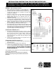
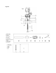
ASSEMBLY THE FIXTURE (FIG.1&FIG.3)
1.
Shut of power at the fuse box or circuit breaker box and
remove the old fixture including the mounting hardware.
2.
Carefully unpack your new fixture and lay out all the parts in
a clean area. Take care not to
misplace any small parts
necessary for installation.
3. Attach the circular strap (H) to the junction
box using the
junction box screws (J
). The side of the mounting plate
marked “GND” must face out.
Mounting screw can be
adjustable if necessary.
4. Thread the wire through the all thread
(A), secure the nipple
on the top of the coupling (B) tightly. Slide
the tube (C) over
the all thread (A) and place
the cap (D) on top of the tube (C).
5. Slide the all thread through the canopy and
place the steel
panel (F) inside the canopy (E), followed
by support cable
(K), lock washer (M), and secure with hex nut (G).
6. The support cable (K)
is provided to support the weight of the
fixture while wiring. Align the fixture to circular strap (H
) and
attach hook on the end of support cable (K) into a
slot located
on circular strap (H). Carefully allow the support cable (K
) to
support the weight of the fixture while wiring.
CONNECTING THE WIRES (FIG. 2)
7. C
onnect the electrical wires as shown in figure 2, making
sure that all wire connectors are secured. If your junction box
has a ground wire (green or bare copper), connect the
fixture’s ground wire to it. Otherwise, connect the fixture’s
ground wire directly to the circular strap (H)
using the green
screw provided.
8. Tuck the wire connectors neatly into the junction b
ox and
then raise the canopy to the ceiling.
COMPLETING THE INSTALLATION (Fig. 1)
9. Slide canopy (E) over mounting screws (I
) and secure with
decorative nuts (L).
10. Place the candle covers (M) over the sockets (N).
11. Install (4) four candelabra base bulbs (O) up to 60 watts each
or CFL or LED equivalent (not included) in accordance with
the fixture specification—
DO NOT EXCEED THE MAXIMUM
WATTAGE RATING! (NE PAS DEPASSER LA PUISSANCE
NOMINALE MAXIMALE!).
Your installation is now complete. Turn on the power supply of the
junction box to test the fixture.
Note: Illustration (Fig. 1) on this manual is for installation
purposes only. It may or may not be identical to the fixture
purchased.
#N7983-420
Fig.1
INSTALLATION INSTRUCTION FOR FIXTURE #N7983-420
WARNING! SHUT POWER OFF AT FUSE OR CIRCUIT BREAKER.
AVERTISSEMENT! COUPER LE COURANT AU NIVEAU DES FUSIBLES OU DU DISJONCTEUR.
Fig.2
Candle cover#CCV21060P-84