METROLOGIC INSTRUMENTS, INC.
Copyright © 2006 by Metrologic Instruments, Inc. All rights reserved. No part of this work may be reproduced, transmitted, or stored in any form or by any means without prior written consent, except by reviewer, who may quote brief passages in a review, or provided for in the Copyright Act of 1976. Products and brand names mentioned in this document are trademarks of their respective companies.
Table of Contents Introduction Product Overview .......................................................................................................................4 Scanner and Accessories...........................................................................................................4 General Features and Characteristics Multifunctional Keypad ...............................................................................................................6 The LCD Screen .......................
3
Introduction Product Overview The SP5500 OptimusS Portable Data Terminals are robust and versatile scanning devices designed to provide exceptional performance, while enduring the demands of everyday use. The lithium-ion rechargeable battery provides the Optimus with more than 100 hours of operation. It is supported by a resourceful set of development tools, including a Windows-based program builder, “C” compiler, and “BASIC” compiler.
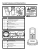
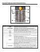
General Features and Characteristics 1 4 9 5 2 3 8 6 7 Figure 1. Scanner Features ITEM NO. Figure 3. Product Label DESCRIPTION 1 Red Output Window (Laser Aperture) 2 Safety and Product label (Figure 3) 3 Speaker for audible indicators 4 LCD display 5 Multi-functional Keypad 6 Charging and communication contacts 7 IR Communication port 8 Battery Compartment release 9 Scan Button 1 6 2 3 4 5 Figure 2. Cradle Features ITEM NO.
General Features and Characteristics Multifunctional Keypad 4 5 6 3 7 2 8 1 Figure 5.Keypad Features ITEM NO. KEY NAME 1 POWER 2 ALPHANUMERIC 3 BS 4 ENTER 5 SCAN 6 ESC 7 ARROW ALPHA() 8 FUNCTION(FN) DESCRIPTION Power On/Off. To prevent an accidental power down, it requires about 1.5 sec of continuous pressing to turn On/Off the power. Alphanumeric These 10 keys can be used for either alpha characters or numerical input.
General Features and Characteristics The LCD Screen The LCD screen of the OptimusS Portable Data Terminal displays program settings, operational parameters, data collected, and much more.
Installation Getting Started The OptimusS Portable Data Terminal (PDT) requires minimal effort to begin functional operation for data collection in any application. In order to get started the unit must have a fresh battery inserted into the battery compartment. 1. Access the battery compartment by removing the battery cover (See Figure 7). To remove the cover, press the cover release down and slide the cover away form the unit. 2.
Installation Basic Operation In order for the Optimus to operate properly, an application program must be loaded onto the PDT. It is possible for the Optimus to power up without at active application. On power up if the Optimus has no application program loaded, then the following Application Program menu options will appear on the display: MENU OPTIONS. Download Activate Upload DESCRIPTION This option allows the user to download application programs (*.SHX), BASIC run-time (bas.ops.
Installation 3. Follow steps a and b a. For the RS232 cable plug the 9 pin serial connector into a serial port on the host device. Plug the opposite end into the communication port of the cradle. b. For the USB cable plug the USB end of the cable into an appropriate communication port on the host device and the opposite end of the cable into the communication port of the cradle*. 4. Power up the Optimus and select the Utilities option. 5. This will open additional menu options.
Installation Data Upload 1. To transfer the data collected select the Utilities option. 2. Select the Transfer Files option on the next menu and then the Send Files option. 3. Re-insert the Optimus unit into the cradle and upload the data to the host device. The OptimusSBT Bluetooth model is similarly connected to the host device and programmed however, there are some key differences in the data collection process.
Installation The System Module The system module on the Optimus is another useful tool included with the Optimus. It provides information about the Optimus and access to the system menu for configuring the Optimus. In order to access the system module, follow the instructions below: 1. With the Optimus powered off press down and hold the 7, 9, and power button. 2. An audible indicator will sound to indicate that the Optimus is powered on. 3. The Optimus will display the system menu.
Installation Settings SETTING Clock Backlight ON Period CPU Speed Powering Off the Terminal Power On Options Key Click System Password DESCRIPTION DEFAULT Set date and time for the system. Set the duration for the keyboard/LCD backlight N/A the light goes off after 20 seconds Set CPU running speed. There are five speeds available: Full speed, half speed, quarter speed, eighth speed and sixteenth speed.
Installation Memory The menu option provides the user with ability to gather information on the amount of memory available on the Optimus, as well as the ability to initialize the memory. This is accomplished by choosing one of the two available selections. 1. Size Info. 2. Initialize Size Info. The Optimus contains two types of memory, SRAM and Flash memory. These two types of memory allow the Optimus to perform operational tasks at an optimal level.
Installation Application The Application module runs on top of the System module. The OptimusS Series Portable Data Terminals are preloaded with the Optimizer’s run-time program and the following menu will be shown upon powering the unit up: Models (SP5502 and SP5535): 1. Run Program 2. Utilities Utilizing the arrow keys select the menu option and execute it by pressing the ENTER key.
Troubleshooting SYMPTOM DESCRIPTION Make sure the battery is inserted and charged. Does not power up after pressing POWER key. Cannot transmit data or programs to/from the terminal Keypad does not work properly Charge the battery and check the charging status. If no charging information shown on the display, reload the battery and check if the battery is properly installed then try again. Call for service if problem persists. Check if the cable is plugged tightly into host device and cradle.
Specifications OPTIMUSS SERIES OPERATIONAL Light Source: Normal Depth of Field: Width of Scan Field: Visible Laser Diode (VLD) @ 650 nm 20 mm - 202 mm 0.33 mm (13 mil) (.75"- 8.75") bar code 290mm (11.4”) @ 222 mm (8.75”) Single-Line Scan Speed: No. of Scan Lines: Min Bar Width: 100 scan lines per second 1 0.127 mm (5.0 mil) Decode Capability: All standard 1-D bar codes including RSS-14, RSS-Expanded, and RSS-14 Limited Print Contrast: No.
Specifications OPTIMUSS SERIES MECHANICAL Width (Unit): 55 mm (2.2") Depth (Unit): 28 mm (1.1") Height (Unit): 137 mm (5.4") Weight (Unit): 4.9 oz (140 g) – including battery Width (Cradle): 92 mm (3.6") Depth (Cradle): 110 mm (4.3") Height (Cradle): 58 mm (2.3") ELECTRICAL Battery Operation: Battery Backup: Operation: Laser Class: EMC: Li-ion 3.
Contact Information and Office Locations Corporate Headquarters Metrologic Instruments, Inc. 90 Coles Road Blackwood, NJ 08012-4683 Tel: 856-228-8100 Fax: 856-228-6673 (Sales) Fax: 856-228-1879 (Marketing) Fax: 856-228-0653 (Legal/Finance) Email: info@metrologic.com European, Middle East and African HQ & Germany Office Eastern Europe and Middle East Metrologic Instruments GmbH Dornierstrasse 2 82178 Puchheim Munich, Germany Tel: 49-89-89019-222 Fax: 49-89-89019-173 Email: info@east.metrologic.
Contact Information and Office Locations South America and Central America Brazil Metrologic do Brasil Ltda. Rua da Paz 2059 CEP 04713-002 Chácara Santo Antônio São Paulo, SP, Brasil Tel: 55-11-5182-8226 Fax: 55-11-5182-8315 Email: info@br.metrologic.com Outside Brazil Metrologic South America Rua da Paz 2059 CEP 04713-002 Chácara Santo Antônio São Paulo, SP, Brasil Tel: 55-11-5182-7273 Fax: 55-11-5182-7198 Email: info@sa.metrologic.
Safety Notices This equipment has been tested and found to comply with the limits for a Class B digital device, pursuant to Part 15 of the FCC Rules. These limits are designed to provide reasonable protection against harmful interference in a residential installation. This equipment generates, uses, and can radiate radio frequency energy and, if not installed and used in accordance with the instructions, may cause harmful interference to radio communications.