METROLOGIC INSTRUMENTS, INC.
Copyright © 2008 by Metrologic Instruments, Inc. All rights reserved. No part of this work may be reproduced, transmitted, or stored in any form or by any means without prior written consent, except by reviewer, who may quote brief passages in a review, or provided for in the Copyright Act of 1976. Trademarks Metrologic is a registered trademark of Metrologic Instruments, Inc. Products identified in this document are hereby acknowledged as trademarks, registered or otherwise, of Metrologic Instruments, Inc.
TABLE OF CONTENTS INTRODUCTION Manual Scope .......................................................................................................................................................................... 1 Product Overview ..................................................................................................................................................................... 1 Model Number Designation......................................................................................
TABLE OF CONTENTS OCIA .................................................................................................................................................................................. 24 Cable Installation (Secondary Metrologic Scanner)................................................................................................................ 26 EAS Deactivation .............................................................................................................................
INTRODUCTION MANUAL SCOPE This guide provides information on the installation, setup and operation of the StratosH® MS2321 and MS2322 scanner models. If the MS2321 scanner has been integrated with a scale, please refer to the Custom Scale Addendum provided for detailed instructions on the appropriate cable connections, communication specifications and calibration procedures required by the scale manufacturer and local Weights and Measures Authorities.
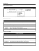
INTRODUCTION MODEL NUMBER DESIGNATION M ODEL N UMBER D ESIGNATION Figure 1. Model Number Designation BASE KIT COMPONENTS B ASE K IT C OMPONENTS Part # Description MS2 3 2 1 * / MS2 3 2 2 * StratosH™ Series Scanner * See model number designation above for detailed information on interface type and window type.
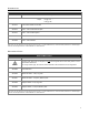
INTRODUCTION O PTIONAL A CCESSORIES Part # Description AC to DC Power Transformer - Regulated Output: +5V @ 1.5A +12V @ 1.5A 46-46812 120V United States and Canada 46-46813 220V – 240V Continental European 46-46814 220V – 240V United Kingdom 46-46817 220V – 240V China 46-46928 220V – 240V Australia Other items may be ordered for the specific protocol being used.
INTRODUCTION GENERAL PRECAUTIONS The following list includes general precautions to remember when handling the StratosH. DO NOT TURN the unit upside down with the platter in place. Figure 2 DO NOT PRESS on the window in the placement platter or the vertical window frame. Figure 3 PLATTER REMOVAL No hardware or tools are required to remove the platter / horizontal scan window (see Figure 4). Refer to the Maintenance section of this manual for additional information on platter replacement.
INTRODUCTION MS2321 / MS2322 SCANNER DESIGN SPECIFICATIONS Design Specifications Operational Light Source: Peak Laser Power: Maximum IR LED Output: Horizontal Depth of Field: Vertical Depth of Field: Scan Speed: No. of Scan Lines: Motor Speed: Min Bar Width: VLD 650 nm <2.2 mW 50μW per IEC 60825-1 measurement procedure 0 mm - 152 mm (0"- 6") for 0.33 mm (13 mil) Bar Code 0 mm - 216 mm (0"- 8.5") for 0.
BASE MODEL CHARACTERISTICS MS2321 Scanner Components Figure 6. MS2321 Components Components ITEM NO.
BASE MODEL CHARACTERISTICS MS2321 Scanner Dimensions Figure 7. MS2321 Dimensions Connector Panel Figure 8. MS2321 Connector Panel Scale ready MS2321 models supply additional connectors for scale and display communication cabling. The use of these connections is dependent on the specific manufacturer of the scale being integrated. Please refer to the Custom Scale Addendum for detailed instructions on the appropriate cable hookups and calibration procedures for local Weights and Measures authorities.
BASE MODEL CHARACTERISTICS MS2321 Scanner Caution and Serial Number Labels Figure 9. MS2321 Label Locations (Top) and Examples (Bottom) Caution: To maintain compliance with applicable standards, all circuits connected to the scanner must meet the requirements for SELV (Safety Extra Low Voltage) according to EN/IEC 60950-1. To maintain compliance with standard CSA C22.2 No.
BASE MODEL CHARACTERISTICS MS2322 Scanner Components Figure 10. MS2322 Components Components ITEM NO.
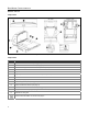
BASE MODEL CHARACTERISTICS MS2322 Scanner Dimensions Figure 11. MS2322 Dimensions Connector Panel Figure 12. MS2322 Connectors Specifications are subject to change without notice.
BASE MODEL CHARACTERISTICS MS2322 Scanner Caution and Serial Number Labels Figure 13. MS2322 Label Locations (Top) and Examples (Bottom) Caution: To maintain compliance with applicable standards, all circuits connected to the scanner must meet the requirements for SELV (Safety Extra Low Voltage) according to EN/IEC 60950-1. To maintain compliance with standard CSA C22.2 No.
INSTALLATION QUICK INSTALLATION OUTLINE The following is a quick preview of the steps required for first time installations. Each item is discussed in detail later in this section. • • • • • • • • • Determine clearance, ventilation and service access requirements. Determine checkout counter layout taking into account package flow, cable routing and power requirements. Choose the mounting option which provides the best cable/power access and unit stability. Unpack the unit.
INSTALLATION UNPACKING THE UNIT 1. Make sure the shipping box is top-side up before opening. 2. Remove the accessories box and check the box’s content for the following items: 3. • Product Manuals • Power Supply • Communication Cables Figure 14 Lift the scanner out of the shipping box by gripping the bottom of the unit on both sides. Important! Do not lift the unit out of the box by gripping the sides of the platter. Figure 15 4. Carefully remove the shipping foam around the unit.
INSTALLATION INSTALLING THE UNIT IN THE COUNTER MS2321 Mounting Diagram (Two Point Support) Figure 18. MS2321 Mounting Diagram, Two Point Support Specifications are subject to change without notice.
INSTALLATION INSTALLING THE UNIT IN THE COUNTER MS2321 Mounting Diagram (Three Point Support) Figure 19. MS2321 Mounting Diagram, Three Point Support Specifications are subject to change without notice.
INSTALLATION INSTALLING THE UNIT IN THE COUNTER MS2322 Mounting Diagram (Two Point Support) Figure 20.
INSTALLATION INSTALLING THE UNIT IN THE COUNTER MS2322 Mounting Diagram (Three Point Support) Figure 21. MS2322 Mounting Diagram, Three Point Support Specifications are subject to change without notice.
INSTALLATION CABLE INSTALLATION (INTERFACE SPECIFIC) RS232 The following steps describe how to properly install the cables for an RS232 StratosH application. The scanner must then be configured to match the host’s RS232 parameters. Cable installation alone does not guarantee that the StratosH will communicate properly with the host system. Configuration bar codes are located in the MetroSelect Configuration Guide (MLPN 00-02407x) and the MS2xxx Stratos Series Configuration Addendum (MLPN 00-02034x). 1.
INSTALLATION CABLE INSTALLATION (INTERFACE SPECIFIC) RS232 xxx* Specifies international connection. See Optional Accessories in the Introduction section of this guide for a complete listing. See power source caution statement on page 11 of this manual. Figure 22.
INSTALLATION CABLE INSTALLATION (INTERFACE SPECIFIC) FULL SPEED USB The following steps describe how to properly install the cables for a Full Speed USB StratosH application. The scanner must then be configured to match the host’s USB parameters. Cable installation alone does not guarantee that the StratosH will communicate properly with the host system.
INSTALLATION CABLE INSTALLATION (INTERFACE SPECIFIC) FULL SPEED USB Step 8 is for USB Serial Emulation Mode or Keyboard Emulation Mode only. 8. Configure the StratosH for Bi-Directional USB Serial Emulation Mode or USB Keyboard Emulation Mode by scanning the appropriate configuration bar codes in the USB section of the MetroSelect Configuration Guide (MLPN 00-02407x). Step 7 must be completed before continuing to step 8 for these features to work properly. xxx* Specifies international connection.
INSTALLATION CABLE INSTALLATION (INTERFACE SPECIFIC) RS485S The following steps describe how to properly install the cables for an RS485S StratosH application. The scanner must then be configured to match the host’s RS485S parameters. Cable installation alone does not guarantee that the StratosH will communicate properly with the host system. Configuration bar codes are located in the MetroSelect Configuration Guide (MLPN 00-02407x) and the MS2xxx Stratos Series Configuration Addendum (MLPN 00-02034x). 1.
INSTALLATION CABLE INSTALLATION (INTERFACE SPECIFIC) RS485S xxx* Specifies international connection. See Optional Accessories in the Introduction section of this guide for a complete listing. See power source caution statement on page 11 of this manual. Figure 24. RS485S Cable Installation Schematic S ® Applicable for IBM Host applications.
INSTALLATION CABLE INSTALLATION (INTERFACE SPECIFIC) OCIA The following steps describe how to properly install the cables for an OCIA StratosH application. The scanner must then be configured to match the host’s OCIA parameters. Cable installation alone does not guarantee that the StratosH will communicate properly with the host system. Configuration bar codes are located in the MetroSelect Configuration Guide (MLPN 00-02407x) and the MS2xxx Stratos Series Configuration Addendum (MLPN 00-02034x). 1.
INSTALLATION CABLE INSTALLATION (INTERFACE SPECIFIC) OCIA xxx* Specifies international connection. See Optional Accessories in the Introduction section of this guide for a complete listing. See power source caution statement on page 11 of this manual. Figure 25.
INSTALLATION CABLE INSTALLATION (SECONDARY METROLOGIC SCANNER) The following steps describe how to properly install the cables between a secondary Metrologic scanner and the StratosH. The StratosH and the secondary scanner must then be configured to communicate properly. Cable installation alone does not guarantee that the StratosH will communicate properly with the host system and secondary scanner.
INSTALLATION CABLE INSTALLATION (SECONDARY METROLOGIC SCANNER) † See Aux power notes on page 26 See power source caution statement on page 11 of this manual. Figure 26.
INSTALLATION EAS DEACTIVATION SW1 and SW2 are the switch banks inside the Checkpoint device that set the deactivation range. The following is a list of Checkpoint recommended switch bank settings. Base Model Checkpoint Recommended Switch Bank Settings MS2321 SW1 & SW2 switches 1 and 6 set to ON MS2322 SW1 & SW2 switches 1 and 6 set to ON All StratosH models have a connector labeled EAS In on the bottom of the unit.
SCANNER OPERATION SCAN ZONE Figure 29. Checker-Side (13 mil) Figure 30. Horizontal Left/Right (13 mil) Specifications are subject to change without notice.
SCANNER OPERATION SCAN ZONE Figure 31. Horizontal Direct (13 mil) Figure 32. Vertical Direct (13 mil) Specifications are subject to change without notice.
SCANNER OPERATION IR ACTIVATION AREA (IR LED OUTPUT) The StratosH’s default power save mode† is Dual Action Power Save Mode #2 (see page 36). This power save mode† turns the laser OFF after a configured period of non-use then turns the motor OFF after thirty-minute intervals. Any movement detected by the IR in the activation area, shown below, will cause the scanner to exit the power save mode.
SCANNER OPERATION INDICATOR DESCRIPTIONS Audible When in operation the StratosH provides audible feedback that indicates the status of the unit and the current scan. Eight settings are available for the tone of the beep (normal, six alternate tones and no tone) plus three volume settings. To change the tone or volume, refer to the Changing the Beeper Tone & Volume section of this manual.
SCANNER OPERATION INDICATOR DESCRIPTIONS Visual Steady White and Blue After a successful scan, the scanner transmits the data to the host device. Some communication modes require that the host inform the scanner when data is ready to be received. If the host is not ready to accept the information, the scanner’s white LED will remain on until the data can be transmitted. Flashing Blue then Flashing White This indicates the scanner is in configuration mode.
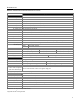
SCANNER OPERATION INDICATOR DESCRIPTIONS Diagnostic Indicator Display There is a two-digit error code display located under the platter near the end of the scanner farthest from the vertical window (see figure below). Figure 35. Error Code Display The following is a list of possible error codes and their meanings. Some errors will require immediate scanner maintenance. ERROR CODE S DESCRIPTION 01 Reserved 02 RAM ERROR – The scanner’s Random Access Memory (RAM) is tested as faulty.
SCANNER OPERATION INDICATOR DESCRIPTIONS Diagnostic Indicator Display ERROR CODE DESCRIPTION 11 SWITCH ERROR – The switch used for volume selection or sleep mode is detected in error (always closed). The condition is self-correcting if possible. If the error persists, return the unit for repair at an authorized service center. The scanning operation can continue with this error active. 21 LASER #1 (VERTICAL) ERROR – The laser in the vertical scanning subsystem denotes a failure.
SCANNER OPERATION POWER SAVE MODES The StratosH has five configurable power save modes. Refer to the MetroSelect Configuration Guide (MLPN 00-02407x) for additional information on Power Save Modes. 1. Blink Power Save Mode: Blinks the laser OFF & ON after a configured period of non-use. When the scanner recognizes a bar code it will exit the Blink mode. 2. Laser Off Power Save Mode: Turns the laser OFF after a configured period of non-use. The motor continues to spin allowing for a faster “wake” up time.
SCANNER OPERATION BEEPER OPTIONS AND BUTTON FUNCTIONS Changing the Beeper Tone Beeper tones may be configured incrementally using the following bar code. The new tone will be heard followed by a short pause. Two more new tones will be heard signifying the new setting has been stored in memory. The silent (no beep) tone is also selectable. Next Beep Tone ³ 9 9 9 9 7 5 Changing the Beeper Volume Volume levels may be configured using the volume button or incrementally using the following bar code.
SCANNER OPERATION STARTUP When the scanner first receives power the white LED will flash, the blue LED will turn on and the scanner will beep once (the white LED will remain on for the duration of the beep). The scanner is now ready to scan. POWER-UP TEST MODE When a StratosH scanner is first powered up, it cycles through a number of self-tests before starting normal operation.
MAINTENANCE PLATTER / HORIZONTAL SCAN WINDOW REPLACEMENT Figure 40. Platter/Horizontal Scan Window Replacement* * See replacement parts on page 3.
MAINTENANCE VERTICAL SCAN WINDOW REPLACEMENT (MLPN 46-46889) Figure 41. Vertical Scan Window Replacement DAILY MAINTENANCE Smudges and dirt can interfere with the proper scanning of a bar code. Therefore, the horizontal and vertical output windows will need occasional cleaning. For the glass window: 1. Spray glass cleaner onto lint free, non-abrasive cleaning cloth. 2. Gently wipe the scanner window. For the inner plastic window: 40 1.
TROUBLESHOOTING The following guide is for reference purposes only. Contact a Metrologic representative at 1-800-ID-METRO or 1-800-436-3876 to preserve the limited warranty terms. Symptom Possible Cause(s) Solution All Interfaces No LEDs, beep or motor spin. No power is being supplied to the scanner. Check the transformer, outlet and the power strip. Make sure the power cable is plugged into the scanner. During power up the unit beeps 3 times. A non-volatile RAM failure.
TROUBLESHOOTING Symptom Possible Cause(s) Solution All Interfaces Check the character length lock. The aspect ratio of the bar code is out of tolerance. Scanner beeps at some bar codes and NOT for others of the same bar code symbology. Check if it is a check digit, character or border problem. The bar code may have been printed incorrectly. The scanner is not configured correctly for this type of bar code. Check if check digits are set properly.
TROUBLESHOOTING Symptom Possible Cause(s) Solution Aux Port Operation With Any Interface The secondary scanner is not functioning. Refer to the user’s guide provided with the secondary scanner. The secondary scanner cable may not be connected to the proper port on the StratosH. The secondary scanner powers up but data is not relayed to the host. Ensure that the secondary scanner is connected to the StratosH’s com port marked “Aux” port. * The StratosH must be configured to enable the auxiliary port.
DEFAULT SETTINGS COMMUNICATION PARAMETERS Many functions of the scanner can be "configured" - that is, enabled or disabled. The scanner is shipped from the factory preconfigured to a set of default conditions. The default parameter of the scanner has an asterisk ( * ) in the charts on the following pages. If an asterisk is not in the default column then the default setting is Off or Disabled. Every interface does not support every parameter.
DEFAULT SETTINGS COMMUNICATION PARAMETERS PARAMETER DEFAULT RSS Expanded Enable Expanded ID “]e0” * RSS Limited Enable RS232 RS485S USB 9 9 9 9 9 9 9 9 9 9 9 9 RSS Limited ID “]e0” * 9 9 9 9 RSS Limited App ID “01” * 9 9 9 9 RSS Limited Check Digit * 9 9 9 9 9 DTS/SIEMENS * DTS/NIXDORF 9 NCR F 9 NCR S 9 Normal 9 9 9 9 Before Transmit 9 9 9 9 Loudest 9 9 9 9 9 9 9 9 9 9 9 9 Razzberry Tone on Timeout 9 9 9 9 Three Beeps on Timeout 9 9
DEFAULT SETTINGS COMMUNICATION PARAMETERS DEFAULT OCIA RS232 RS485S USB * 9 9 9 9 Same Symbol Rescan Timeout: 500 msecs Configurable in 50 msec steps (MAX 6.
DEFAULT SETTINGS COMMUNICATION PARAMETERS OCIA RS232 RS485S USB EAN 128 Enable 9 9 9 9 Enable French Pharma 9 9 9 9 Enable Matrix 2 of 5 Check Digit 9 9 9 9 Enable Hong Kong 2 of 5 9 9 9 9 Enable Alpha Telepen 9 9 9 9 Telepen Convert Lead ‘^L’ to ‘E’ 9 9 9 9 Enable Code 11 Check Digit 9 9 9 9 PARAMETER DEFAULT Parity Baud Rate Space 9 9600 9 9 8 Data Bits 7 Data Bits * 9 Stop Bits 2 9 RTS / CTS Enabled 9 Message RTS 9 * Character RTS S 9 ACK / NAK
DEFAULT SETTINGS COMMUNICATION PARAMETERS PARAMETER DEFAULT OCIA RS485S USB STX Prefix 9 9 TAB Prefix 9 9 Metrologic Prefix 9 9 UPC Prefix 9 9 ETX Suffix 9 9 TAB Suffix 9 9 Carriage Return Suffix * 9 9 Line Feed Suffix * 9 9 9 9 UPC Suffix 9 9 st 9 9 nd Start LRC on 2 Byte 9 9 ‘c’ Prefix for UPC 9 9 ‘$’ Prefix for UPC 9 9 Transmit LRC Start LRC on 1 Byte Configurable Prefix Characters 10 avail 9 9 Configurable Suffix Characters 10 avail 9 9 Multiple
DEFAULT SETTINGS COMMUNICATION PARAMETERS OCIA RS232 RS485S USB Five Digit Redundancy 9 9 9 9 Enable Coupon Code 128 9 9 9 9 PARAMETER DEFAULT Transmit Coupon ‘]C1’ * 9 9 9 9 Group Separator * 9 9 9 9 Coupon Code Can Begin with ’4’ 9 9 9 9 Enable EAN-99 Coupon Code 9 9 9 9 Bookland Supplements 9 9 9 9 French 378/379 Supplements 9 9 9 9 German 434/439 Supplements 9 9 9 9 Convert Bookland to ISBN 9 9 9 9 Bookland 979 Supplements 9 9 9 9 Convert 97
DEFAULT SETTINGS COMMUNICATION PARAMETERS Default settings for “Aux” interface The secondary scanner and the StratosH series always communicates via RS232. Data is relayed to the host via various primary interfaces.
SCANNER AND CABLE TERMINATIONS SCANNER PINOUT CONNECTIONS The StratosH scanner terminates to 10-pin modular jacks located on the bottom of the unit. The serial number label indicates the model number and interface of the scanner. EAS Pin Auxiliary RS232 In Function Pin Function 1 EAS In 1 Ground 2 EAS Out 2 RS232 Receive Input DC Power Pin Function 3 RS232 Transmit Output 4 RS232 RTS In 5 RS232 CTS Out 1 12VDC 6-8 No Connect 2 3 Ground 5.2VDC 9 10 +5V Out No Connect Figure 42.
SCANNER AND CABLE TERMINATIONS SCALE READY MS2321 MODELS – ADDITIONAL PINOUT CONNECTIONS There are four additional 10-pin modular jacks located on the bottom of the of the MS2321 StratosH models that may be used for an integrated scale application and the use of a remote display. Please keep in mind that every application is unique. The use of these connections depends on the specifications of the scale’s manufacturer. The following pinouts are for reference only.
SCANNER AND CABLE TERMINATIONS CABLE CONNECTOR CONFIGURATIONS The following cables are examples of some of the standard cables that may be shipped with the StratosH scanner. Please keep in mind that every application is unique and the cables received with the StratosH may be custom cables that are not shown below.
SCANNER AND CABLE TERMINATIONS CABLE CONNECTOR CONFIGURATIONS Aux Port Configuration Cable*, MLPN 57-57008x-N-3 Function** Pin 1 No Connect 2 Output from Scanner 3 Input to Scanner 4 No Connect 5 Ground 6-9 9-Pin D-Type Connector No Connect RS232 LSO/AUX Cable, MLPN 57-57099x -3 Pin Function † 1 Signal Ground 2 RS232 from Aux / Secondary Scanner 3 RS232 to Aux / Secondary Scanner 4 RTS from Aux / Secondary Scanner 5 CTS to Aux / Secondary Scanner 6-8 No Connect 9 +5VDC – Transf
REGULATORY COMPLIANCE SAFETY ITE Equipment IEC 60950-1, EN 60950-1 Laser Laser Class 1: IEC 60825-1:1993+A1+A2, EN 60825-1:1994+A1+A2 Caution Use of controls or adjustments or performance of procedures other than those specified herein may result in hazardous laser light exposure. Under no circumstances should the customer attempt to service the laser scanner. Never attempt to look at the laser beam, even if the scanner appears to be nonfunctional.
REGULATORY COMPLIANCE EMC Emissions FCC Part 15, ICES-003, CISPR 22, EN 55022 Immunity CISPR 24, EN 55024 Changes or modifications not expressly approved by the party responsible for compliance could void the user’s authority to operate the equipment. Class A Devices The following is applicable when the scanner cable is greater in length than 3 meters (9.8 feet) when fully extended: Les instructions ci-dessous s’appliquent aux cables de scanner dépassant 3 métres (9.
REGULATORY COMPLIANCE EMC Changes or modifications not expressly approved by the party responsible for compliance could void the user’s authority to operate the equipment. Class B Devices The following is applicable when the scanner cable is less than 3 meters (9.8 feet) in length when fully extended: Les instructions ci-dessous s’appliquent aux cables de scanner ne dépassant pas 3 métres (9.
LIMITED WARRANTY ® The MS2300 StratosH Series scanners are manufactured by Metrologic at its Suzhou, China facility. The MS2300 StratosH Series scanners have a three (3) year limited warranty from the date of manufacture. Metrologic warrants and represents that all MS2300 StratosH Series scanners are free of all defects in material, workmanship and design, and have been produced and labeled in compliance with all applicable U.S.
PATENTS Patent Information This METROLOGIC product may be covered by, but not limited to, one or more of the following U.S. Patents: U.S. Patent No.
INDEX A G AC ...................................................................... see power application .................................................................34, 43 audible...........................................................see indicators AUX.......................................................................6, 43, 51 ground.......................................................................51–54 B beep ..............................................................
INDEX S U safety.........................................................................55, 57 scale................................................................................12 scan pattern ......................................................................5 scan speed........................................................................5 scan zone..................................................................29–30 scanner pinouts.............................................................
62
April 2008 Printed in the USA 00 - 02270C