METROLOGIC INSTRUMENTS, INC.
LOCATIONS CORPORATE HEADQUARTERS NORTH AMERICA EUROPEAN, MIDDLE EAST & AFRICAN HEADQUARTERS USA, NEW JERSEY GERMANY, MUNICH Metrologic Instruments, Inc. Tel: 1-800-ID-METRO Fax: 856-228-6673 Email: info@metrologic.com Metrologic Instruments GmbH Tel: 49-89-89019-0 Fax: 49-89-89019-200 Email: info@europe.metrologic.com SOUTH AMERICA, BRAZIL SÃO PAULO GERMANY, MUNICH Metrologic do Brasil Ltda. Tel: 55-11-5182-8226 Fax: 55-11-5182-8315 Email: info@br.metrologic.
TABLE OF CONTENTS Introduction........................................................................................................... 1 Scanner and Accessories..................................................................................... 2 Operation Test...................................................................................................... 4 Installing the Scanner to the Host System MS9520-00/9/11/14/41 AND MS9540-00/9/11/14/41 .........................................
TABLE OF CONTENTS IR Activation ....................................................................................................... 25 Applications and Protocols ................................................................................. 26 Troubleshooting Guide ....................................................................................... 27 RS232 Demonstration Program ......................................................................... 30 Design Specifications Operational..........
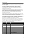
INTRODUCTION ® The Voyager MS9500 Series single-line hand-held scanners include both the MS9520 and MS9540. ® ® The VoyagerCG MS9540 features Metrologic’s patented CodeGate technology. CodeGate is an intuitive scanning system that is ideal for all scanning applications, including menu-scanning, point-of-sale, document processing, and inventory control. CodeGate works hand-in-hand with Metrologic’s patented automatic-triggering scheme.
SCANNER AND ACCESSORIES BASIC KIT Part # Description MS9500 Voyager Series Scanner 00-02544 MetroSelect Single-Line Configuration Guide 00-02410 MS9500 Voyager Series Single-Line Hand Held Laser * Scanner Installation and User’s Guide * * Available on the Metrologic website - www.metrologic.com OPTIONAL ACCESSORIES Part # Description AC to DC Power Transformer- Regulated 5.2VDC @ 650 mA output.
SCANNER AND ACCESSORIES OPTIONAL ACCESSORIES Part # 53-53213 53-53214 Description USB Power/Communication Cable, 3 m (10’) coiled cord, long strain relief, gray USB Power/Communication Cable, 5 m (10’) coiled cord, long strain relief, gray Not for use with Low Speed USB scanners. Use with Full Speed USB scanners only. MX009-2** MX009 USB Converter Cable MVC** Metrologic Voltage Converter Cable +12VDC to +5.2VDC or -12VDC to +5.
OPERATIONAL TEST 1. Connect the 10-pin RJ45 male connector into the jack on the Voyager or VoyagerCG. You will hear a ‘click’ when the connection is made. 2. Connect the L-shaped plug of the power supply into the power jack on the PowerLink cable. 3. Connect the power supply into an AC outlet. Make sure the AC input requirements of the power supply match the AC outlet. 4. 5. When the Voyager is ready to scan, the green LED will turn on, the red LED will flash and the scanner will beep once.
INSTALLING THE SCANNER TO THE HOST SYSTEM MS9520-00/9/11/14/41 AND MS9540-00/9/11/14/41 1. Turn off the host system. 2. Connect the 10-pin RJ45 male connector into the jack on the Voyager or VoyagerCG. You will hear a ‘click’ when the connection is made. If the scanner is receiving power from the host system, skip to step #5. 3. Connect the L-shaped plug of the power supply into the power jack on the PowerLink cable. 4. Make sure the AC input requirements of the power supply match the AC outlet.
INSTALLING THE SCANNER TO THE HOST SYSTEM KEYBOARD WEDGE MS9520-47 AND MS9540-47 1. Turn off the PC. 2. Connect the 10-pin RJ45 male connector into the jack on the Voyager or the VoyagerCG. You will hear a ‘click’ when the connection is made. 3. Connect the L-shaped plug of the power supply into the power jack on the PowerLink cable. If the scanner is receiving power from the host system, skip to step #5. 4. Make sure the AC input requirements of the power supply match the AC outlet.
INSTALLING THE SCANNER TO THE HOST SYSTEM STAND ALONE KEYBOARD 1. Turn off the host system. 2. Connect the 10-pin RJ45 male connector into the jack on the Voyager or VoyagerCG. You will hear a ‘click’ when the connection is made. If the scanner is receiving power from the host system, skip to step #5. 3. Connect the L-shaped plug of the power supply into the power jack on the PowerLink cable. 4. Make sure the AC input requirements of the power supply match the AC outlet.
INSTALLING THE SCANNER TO THE HOST SYSTEM INTEGRATED USB: FULL SPEED MS9520-40 AND MS9540-40 LOW SPEED POS MS9520-39 AND MS9540-39 LOW SPEED HID MS9520-38 AND MS9540-38 1. Turn off the host system. 2. Connect the 10-pin RJ45 male connector of the USB cable into the jack on the Voyager or VoyagerCG. You will hear a ‘click’ when the connection is made. 3. Connect the other end of the USB cable to the host USB port. 4. Turn on the host system.
THE POWERLINK CABLE DISCONNECTING THE POWERLINK CABLE Before removing the cable from the scanner, Metrologic recommends that the power on the host system is off and the power supply has been disconnected from the PowerLink cable. Figure 8. 1. Locate the small ‘pin-hole’ on the top of the unit near the bottom of the Voyager logo. 2. Bend an ordinary paperclip into the shape shown above. 3. Insert the paperclip (or other small metallic pin) into the small ‘pin-hole’. 4. You will here a faint ‘click’.
THE MS9540 VOYAGERCG® SERIES HOW TO USE CODEGATE AND THE MANUAL ACTIVATION MODE CODEGATE ® MANUAL ACTIVATION MODE* * This feature is not a default setting. Refer to the MetroSelect Configuration Guide for instructions on enabling the Manual Activation Mode. Figure 10a. Figure 10b.
STAND KITS Free Standing Kits #46-46128 Contains: c. a. a. Stand (MLPN 36-00454)................................Qty 1 b. Apron (MLPN 50-50440) ...............................Qty 1 c. Screw, M3 x 6 mm (MLPN 18-18670)............Qty 2 d. Washer, #5 x .5 OD (MLPN 18-18671) ..........Qty 2 e. Stand Anchor (MLPN 50-50449) ...................Qty 1 f. M3 x 20 mm Set Screw (MLPN 18-18672).....Qty 1 d. b. e. f. Figure 13. Optional Hard Mount Accessory Kit #46-46351 a.
ASSEMBLING THE STAND There are two options for assembling the stand. The first option is a selfsupporting stand that can be moved freely about on the countertop. The second option is used if the stand will be bolted or hard-mounted to the countertop. Stand Option 1: Self-Supported Stand Kit #46-46128 Apron Step 1 Slide the apron (MLPN 50-50440) over the stand (MLPN 36-00454). Stand Figure 17. Step 2 Apron Position the stand so that it sits under the tab on the apron.
ASSEMBLING THE STAND Stand Option 2: Hard-Mount Kits #46-46128, #46-46351 and MS951 Stand Replacements Anchor from Kit #46-46128 Base Assembly from Kit #46-46351 or MS951 Stand Base Step 3 Screw the stand anchor (MLPN 50-50449) onto the base assembly until it sits flush. Figure 21. Step 4 Remove the logo plate on the stand by gently using an exacto knife to release the plate hook. Figure 22. Step 5 Position the stand over the base assembly. Figure 23. Step 6 Figure 24.
ASSEMBLING THE STAND Wall Mount, Option 1: For Kit #46-46433 or #46-46508 Step 1 Drill two #39 pilot holes 3.00” apart. Step 2 Attach the Wall Mount Hanger to the wall with the two #8 wood screws provided. Figure 26. Wall Mount, Option 2: Kit #46-46508 Step 1 Attach the Wall Mount Base to the Wall Mount Hanger with the two 4.8 x 13 mm self-tapping screws. Step 2 Remove one side of the protective backing from the double-sided adhesive tape. Figure 27.
SCANNER PARTS Yellow LED* Red LED** CodeGate Button* Green LED** MS9500 Top View Output Window Cable Connection MS9500 Side View * This feature is not available on the MS9520. ** In some custom units the standard green LED has been replaced with a blue LED and the red LED has been replaced with a white LED. Figure 29.
AUDIBLE INDICATORS When the Voyager is in operation, it provides audible feedback. These sounds indicate the status of the scanner. Eight settings are available for the tone of the beep (normal, 6 alternate tones and no tone). To change the beeper tone, refer to the MetroSelect Single-Line Configuration Guide or MetroSet2’s help files. One Beep When the scanner first receives power, the green* LED will turn on, then the red* LED will flash and the scanner will beep once.
VISUAL INDICATORS The MS9540 has three LED indicators (green, red and yellow) located on the head of the scanner. The MS9520 has two LED indicators (green* and red*) located on the head of the scanner. When the scanner is on, the flashing or stationary activity of the LEDs indicates the status of the current scan and the scanner. Green*, Red* & Yellow (MS9540’s Only) LEDs are off The LEDs will not be illuminated if the scanner is not receiving power from the host or transformer.
FAILURE MODES Flashing Green* and one Razzberry Tone This indicates the scanner has experienced a laser subsystem failure. Return the unit for repair to an authorized service center. Flashing Red* and Green* with Two Razzberry Tones This indicates the scanner has experienced a scanning mechanism failure. Return the unit for repair to an authorized service center.
PROGRAMMING MODES The MS9500 Voyager has 3 modes of programming. ¾ Bar Codes Voyager or Voyager CG can be configured by scanning the bar codes ® located in the MetroSelect Single-Line Configuration Guide (MLPN 0002544). Please refer to this guide for instructions. This manual can be downloaded for FREE from Metrologic’s website (www.metrologic.com). ¾ MetroSet 2 This user-friendly Windows-based configuration program allows you to simply ‘point-and-click’ at the desired scanner options.
PROGRAMMING MODES 4. During programming, the motor and laser turn off. YOU CANNOT SCAN A BAR CODE WHILE IN SERIAL PROGRAM MODE. 5. There is a 20 second window between commands. If a 20 second timeout occurs, the scanner will send a [nak] and you must start over. 6. To enter serial program mode, send the following command [stx]999999[etx]. 7. To exit serial program mode, send the following command [stx]999999[etx], the scanner will respond with an [ack] followed by 3 beeps. 8.
PROGRAMMING MODES EXAMPLE #3: The following example shows the events that occur when an invalid bar code is sent. This sample will load the factory default settings and then set the baud rate to 19200.
UPGRADING THE FLASH ROM FIRMWARE The MetroSet2 program is a functional component of Metrologic’s new line of Flash- based scanners. This program allows the user of a Metrologic scanner to quickly upgrade to a new or custom version of software. It requires the use of a personal computer running under Windows 95 or greater and the use of a communication port. The user merely connects the scanner to a communications port of the PC, launches the MetroSet2 program, and blasts off to new software upgrades.
LABELS Each scanner has a label on the back of the unit. This label has the model number, date of manufacture, serial number, CE and caution information. The following is an example of this label: EVITER TOUTE EXPOSITION-Lumiere laser emis par cette overture AVOID EXPOSURE –Laser light is emitted from this aperture Patent Information-See Manual FCC and ICES-003 Information-See Manual Warranty VOID if case opened. Contains no user serviceable components. Complies with 21CFR 1040.10 & 1040.
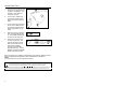
DEPTH OF FIELD Figure 31. Minimum Bar Code Element Width A B C D E F G H J K mm .13 .15 - - .19 - .25 .33 .53 - mils 5.2 5.7 - - 7.
IR ACTIVATION Figure 32.
APPLICATIONS AND PROTOCOLS The model number on each scanner includes the scanner number and factory default communications protocol.
TROUBLESHOOTING GUIDE The following guide is for reference purposes only. Contact a Metrologic representative at 1-800-ID-Metro or 1-800-436-3876 to preserve the limited warranty terms. Symptoms Possible Causes Solution All Interfaces No power is being supplied to the unit. Check the transformer, the outlet and power strip. Make sure the cable is plugged into the unit. No power is being supplied to the unit from host. Some host systems cannot supply enough current to power Voyager.
TROUBLESHOOTING GUIDE Symptoms Possible Causes Solution The unit powers up, but does not scan and/or beep. The bar code being scanned does not satisfy the programmed criteria for character length lock or minimum length. The unit scans a bar code, but locks up after the first scan and the red* LED stays on. The unit is configured to support some form of host handshaking but is not receiving the signal.
TROUBLESHOOTING GUIDE Symptoms Possible Causes Solution The unit scans but the data is not correct. The unit’s configuration is not correct. Make sure that the proper PC type AT, PS2 or XT is selected. Verify the correct country code and data format is selected. Adjust the inter-character delay symptom. The unit is transmitting each character twice. The unit’s configuration is not correct. Increase the interscan code delay setting. Adjust whether the F0 break is transmitted.
RS232 DEMONSTRATION PROGRAM If an RS232 scanner is not communicating with your IBM compatible PC, key in the following BASIC program to test that the communication port and scanner are working. This program is for demonstration purposes only. It is only intended to prove that cabling is correct, the COM port is working, and the scanner is working. If the bar code data displays on the screen while using this program, it only demonstrates that the hardware interface and scanner are working.
DESIGN SPECIFICATIONS MS9500 Series Specifications OPERATIONAL Light Source Visible Laser Diode 650 nm Laser Power: Less than 1 mW (peak) Depth of Scan Field: Scan Speed: Scan Pattern: Minimum Bar Width: 0 mm - 203 mm (0" - 8") for 0.330 mm (13 mil) bar code@ default setting 72 scan lines per second Single scan line 0.127 mm (5.
DESIGN SPECIFICATIONS MS9500 Series Specifications MECHANICAL Length: 198 mm (7.8”) Width: Handle - 45 mm (1.8”), Head - 78 mm (3.1”) Depth: 40 mm (1.6”) Weight: 149 g (5.25 oz) ELECTRICAL Input Voltage: Power: Current: DC Transformers: Laser Class: EMC: 5VDC ± 0.25V Operating = 0.825 W, Standby = 0.600 W Operating = 165 mA @ 5VDC, Standby = 120 mA @ 5VDC Class 2; 5.
DEFAULT SETTINGS Many functions of the scanner can be “configured” or enabled/disabled. The scanner is shipped from the factory configured to a set of default conditions. All default parameters of the scanner have an asterisk ( * ) marked in the default column. If an asterisk is not in the default column then the default setting is off or disabled. Every interface does not support every parameter. A check mark (9) will appear in the interface column if it supports the parameter listed.
DEFAULT SETTINGS Parameter Default OCIA RS232 Light Pen IBM KBW 46xx USB Laser Emulation Mod 43 Check on Code 39 9 9 9 9 9 9 9 MSI-Plessy 10/10 Check Digit 9 9 9 9 9 9 9 9 9 9 9 9 9 9 9 9 9 9 9 9 9 Variable 9 9 9 9 9 9 9 3 9 9 9 9 9 9 9 None 9 9 9 9 9 9 9 MSI-Plessy Mod 10 Check Digit * Paraf Support ITF ITF Symbol Lengths Minimum Symbol Length Symbol Length Lock 9 9 Spaces High as Code 39 9 9 Bars High as Scanned 9 9 Spaces High as Sca
DEFAULT SETTINGS Parameter Default Same symbol rescan timeout: 750 msecs OCIA RS232 Light Pen IBM KBW 46xx USB Laser Emulation 9 9 9 9 9 9 9 9 9 9 9 9 9 9 Same symbol rescan timeout: 1000 msecs 9 9 9 9 9 9 9 No Same symbol timeout 9 9 9 9 9 9 9 Infinite Same symbol timeout 9 9 9 9 9 9 9 1 msecs 10 msecs in KBW 9 9 9 9 9 9 9 Number of scan buffers (maximum) 4 9 9 9 9 9 9 9 Transmit UPC-A check digit * 9 9 9 9 9 9 9 Transmit UPC-E check d
DEFAULT SETTINGS Parameter Default OCIA RS232 Light Pen IBM KBW 46xx Transmit Sanyo ID Characters 9 9 Nixdorf ID 9 9 LRC Enabled 9 9 UPC Prefix 9 9 UPC Suffix 9 9 Carriage Return * 9 9 Line Feed-Disabled by default in KBW * 9 9 Tab Prefix 9 9 Tab Suffix 9 9 “DE” Disable Command 9 “FL” Laser 9 Enable Command 9 DTR Handshaking support 9 RTS/CTS Handshaking 9 Character USB Laser Emulation 9 * Message RTS/CTS 9 XON/XOFF Handshaking 9 ACK/NAK 9 Two Digit Sup
DEFAULT SETTINGS Parameter Default 100 msec to Find Supplement Programmable in 100 msec steps (max 800 msec) * Coupon Code 128 OCIA RS232 Light Pen IBM KBW 46xx USB Laser Emulation 9 9 9 9 9 9 9 9 9 as code 39 9 9 9 as code 39 † Programmable Code Lengths 7 avail 9 9 9 9 9 9 9 † Code Selects with programmable Code Length Locks 3 avail 9 9 9 9 9 9 9 Programmable Prefix characters 10 avail 9 9 Suffix characters 10 avail 9 9 9 9 9 9 Prefixes for Individual Co
SCANNER AND CABLE TERMINATIONS Scanner Pinout Connections The MS9520 and MS9540 scanner interfaces terminate to a 10-pin modular jack. The serial # label indicates the interface enabled when the scanner is shipped from the factory.
SCANNER AND CABLE TERMINATIONS MS9520/40-9 OCIA Pin 1 2 3 4 5 6 7 8 9 10 Function 1 10 Ground RS232 Transmit Output RS232 Receive Input RDATA RDATA Return Clock In Clock Out Clock in Return/Clock out Rtrn +5VDC Shield Ground MS9520/40-00 Laser Emulation Pin 1 2 3 4 5 6 7 8 9 10 Function Ground RS232 Transmit Output RS232 Receive Input Flip Sense/Start of Scan Output Proximity Detect/Trigger Emulation Output Scan/Laser Enable Input Reserved Data Out +5VDC Shield Ground MS9520/40-14 RS232 Pin 1 2 3 4 5
SCANNER AND CABLE TERMINATIONS Cable Connector Configurations (Host End) “Standard” PowerLink Cable 53-53xxx coiled or 54-54xxx straight Pin Function 1 Shield Ground 2 RS232 Transmit Output 3 RS232 Receive Input 4 DTR Input/Light Pen Source 5 Power/Signal Ground 6 Light Pen Data (DSR Out for -14 interfaces) 9 5 6 1 9-Pin D-Type Connector 7 CTS Input 8 RTS Output 9 +5VDC Stand Alone Keyboard PowerLink Cable 53-53020 Pin Function 1 PC Data 2 NC 3 4 Power Ground +5VDC PC Power to KB
SCANNER AND CABLE TERMINATIONS Cable Connector Configuration (Host End) Keyboard Wedge PowerLink Cable 53-53002 or 54-54002 Pin Function 1 Keyboard Clock 2 Keyboard Data 3 4 5 Pin 1 2 3 4 5 6 No Connect Power Ground +5 Volts DC Function PC Data No Connect Power Ground +5 Volts DC PC Clock No Connect 4 2 5 1 3 5-Pin DIN, Female 2 1 4 3 6 5 6-Pin DIN, Male Metrologic will supply an adapter cable with a 5-pin DIN male connector on one end and a 6-pin mini DIN female connector on the other.
LIMITED W ARRANTY The MS9500 series scanners are manufactured by Metrologic at its Blackwood, New Jersey, USA facility. The MS9500 series scanners have a five (5) year limited warranty from the date of manufacture.
LASER AND PRODUCT SAFETY Notice This equipment has been tested and found to comply with the limits for a Class B digital device, pursuant to Part 15 of the FCC rules. These limits are designed to provide reasonable protection against harmful interference in a residential installation. This equipment generates, uses and can radiate radio frequency and, if not installed and used in accordance with the instruction, may cause harmful interference to radio communications.
LASER AND PRODUCT SAFETY Caution Caution Use of controls or adjustments or performance of procedures other than those specified herein may result in hazardous laser light exposure. Under no circumstances should the customer attempt to service the laser scanner. Never attempt to look at the laser beam, even if the scanner appears to be nonfunctional. Never open the scanner in an attempt to look into the device. Doing so could result in hazardous laser light exposure.
PATENTS Patent Information This METROLOGIC product may be covered by one or more of the following US Patents: US Patent No.
INDEX A G AC Input/Outlet......................5, 6, 7 Accessories ...................................2 Adapter..........................................2 Approvals ....................................23 Audible ..................................16–18 Green LED ............ 4, 16–18, 27–29 B I Beep............... 4, 16–18, 20, 21, 22, 27–29, 34 Indicators Audible .............................. 16–18 LED ............. 4, 15, 16–18, 27–29 Installation............................. 42, 43 Interfaces ....
INDEX P T Parameter..............................33–37 Parts ........................................2, 15 Pin Assignments....................38–41 Port................................................6 Power Supply ............4–8, 9, 22, 27 PowerLink............................4–7, 41 Programming......... 4, 19, 20, 26, 29 Termination ................................... 6 Terminations ......................... 38–41 Tones .................................... 16–18 Transformers...........................
NOTES
March 2004 Printed in the USA 00 - 024 10E