METROLOGIC INSTRUMENTS, INC.
LOCATIONS Corporate Headquarters North America Metrologic Instruments, Inc. 90 Coles Road Blackwood, NJ 08012-4683 Customer Service: 1-800-ID-METRO Tel: 856-228-8100 Fax: 856-228-6673 Email: info@metrologic.com Internet: www.metrologic.com European Headquarters Germany, Middle East and Africa Metrologic Instruments GmbH Dornierstrasse 2 82178 Puchheim b. Munich, Germany Tel: +49 89 89019 0 Fax: +49 89 89019 200 Email: info@europe.metrologic.com Germany Email: info@de.metrologic.
TABLE OF CONTENTS Introduction........................................................................................................... 1 Scanner and Accessories..................................................................................... 2 Scanner Connections to the Host ......................................................................... 3 Configuration of the Scanner to the Host System................................................. 4 Cloning Feature ......................................
INTRODUCTION Metrologic's MS860 and MS863 laser bar code Scanners are high-speed, aggressive in-counter scanners. Both models have compact, durable housings for use with applications where counter top space is limited. The MS860 and MS863 autodiscriminate all standard bar codes. Each model includes a code-correcting feature (MECCA©) that enables the scanner to decode damaged or truncated codes on the first pass.
SCANNER AND ACCESSORIES • MS860 or MS863 Laser Bar Code Projection Scanner • Installation and User’s Guide .................................................... MLPN 00-02202 • ® ScanSelect Scanner Programming Guide ............................... MLPN 00-02186 • Volume Control Card ................................................................. MLPN 00-02346 • Installation Plate for MS860 models only ................................... MLPN 45-45471 Optional Accessories • Power Supply .........
SCANNER CONNECTIONS TO THE HOST To avoid potential problems, do not power up the scanner until the communication cable is secured to the host. 1. Turn off the host system. 2. Connect the 25-pin D-type connector on the scanner’s head cable to the communication cable. 3. Connect the other end of the communication cable to the host device. 4. If the scanner will not receive power from a transformer, skip to Step 5.
CONFIGURATION OF THE SCANNER TO THE HOST SYSTEM The MS860/MS863 is shipped from the factory programmed to a set of default conditions noted in the Default Settings section of this guide and in the ScanSelect® Scanner Programming Guide provided. The default settings in the ScanSelect guide have an asterisk that appears before the brief definition next to the bar code. Since each host system is unique, the scanner will need to be configured to match the specific host system’s requirements.
CLONING FEATURE The cloning feature is used to program several scanners with the same settings. To clone a scanner: 1. Turn OFF the power to both scanners by unplugging the transformers. 2. Connect the cloning cable (MLPN 51-51544) between the two scanners. 3. Turn ON the power to both scanners by plugging in the transformers. 4. When each scanner is ready, scan the cloning bar code with the scanner that has the settings that need to be transferred to the other scanner.
VERSION 11 IBM 46XX SCANNER Output Format: IBM RS-485 serial input/output for the 4680 and 4690 (46XX) point-of-sale terminals The Version 11 46XX interface can be used in several different ways. Both the 46XX terminal and the scanner must be configured to match each other. Warning: Power to the scanner and 46XX terminal should be turned off before making physical connection. The 4680 and 4690 series terminals have different types of physical ports for connecting bar code scanners.
CONFIGURING THE MS860-11/MS863-11 SCANNER Located in the Version 11 scanner are two computer boards. One computer board is for decoding and the other for 46XX IO processing. The decode board is configured using ScanSet or ScanSelect while the IO board is configured with an internal DIP Switch bank.
CONFIGURING THE IBM 46XX The 4683 and 4693 terminals are configured on the store controller. The 4684 and 4694 terminals are typically configured on the individual terminals. Follow the appropriate guide for your type of equipment. IBM 4683 and 4693 Terminals Driven by a 46XX Store Controller Running 4680.OS or 4690.OS Access the terminal configuration menu on the store controller. If not already selected, select an IBM 1520 laser hand scanner (4680.
VERSION 17 KEYBOARD WEDGE SCANNER The MS860/MS863 scanner (version 17) provides keyboard emulation by converting the scanned bar code data to the PC keyboard scan code equivalent.
CONNECTION OF A MS860-17 SCANNER TO A PC 1. If the PC is on, exit your application and turn the PC off. 2. Disconnect the keyboard from the PC. Plug the Keyboard Wedge cable to the PC and the keyboard. Use the adapter cable if necessary. 3. Connect the 25-pin D-type connector on the scanner’s head cable to the Keyboard Wedge cable. 4. Check the AC input requirements of the transformer to make sure the voltage matches the AC outlet.
OPTIONAL IN-COUNTER MOUNTING OPTIONS FOR THE MS860 Metrologic has designed three plates to accommodate in-counter installation of the MS860. Included automatically with the purchase of the MS860 is Metrologic part #45-45471, Installation Plate. The universal and replacement plates are available for an additional charge. Contact the distributor, dealer or Metrologic customer service representative to order one of these plates.
VERTICAL STAND KIT Vertical Stand Kit, MLPN 45-45472 includes: a. b. c. Vertical Stand #6-32 x 3/8” Phillips Head Screw #8 x 1.00” Round Head Wood Screw [ MLPN 45-45472 ] [ MLPN 18-18317 ] [ MLPN 18-18057 ] Qty. 1 Qty. 2 Qty. 3 Installation Orientation Note: The arrow on the top of the scanner indicates the direction that items must be presented to the scanner. 1. Drill four #39 pilot holes into the counter top (See Figure 2). 2.
SCANNER PARTS n o p q r s t Touch Plate When a specified time has elapsed without any scanning, the unit will enter a “standby” mode. Touching the touch plate arrow on the top cover will reactivate the scanner. Red LED When the red LED flashes ON, the scanner has read a bar code successfully. When the red light turns OFF, communication to the host is complete. Green LED When the green LED is ON, this indicates the unit is receiving power and the laser is ON.
The MS860 TOUCH PLATE The MS860 will enter “standby” when it remains dormant for a time. When the scanner’s computer is on “standby," touching the touch plate will “wake up” the scanner and activate the laser. When the green LED comes on, the scanner is powering up for full operation. After approximately three seconds, the scanner will be ready to operate. The default touch plate timeout is ten minutes.
VISUAL INDICATORS There is a red and green LED at the top of the scanner. When the scanner is on, the flashing or stationary activity of the LEDs indicates the status of the scan and scanner. Steady Green When the laser is on, the green LED is also on. This occurs when the touch plate has been touched. The green LED will remain on until the touch plate timeout elapses or until the scanner turns off.
VISUAL INDICATORS Signaux optiques Sur la partie supérieure du scanner se trouvent une diode LED rouge et une diode LED verte. Quand le scanner est sous tension, les diodes rouge et verte clignotantes ou allumées vous informent sur l'état du scanner. Ni la diode rouge, ni la diode verte n'est allumée Il existe deux raisons possibles pour que les diodes ne s'allument pas.
VISUAL INDICATORS Optische Anzeigen Auf dem Scanner befinden sich eine rote und eine grüne Leuchtdiodenanzeige. Bei eingeschaltetem Scanner geben Ihnen die blinkenden oder feststehenden Leuchtdiodenanzeigen Aufschluß über den Abtast- und Scannerstatus. Weder rote noch grüne Leuchtdiodenanzeige Es gibt zwei mögliche Gründe, weshalb die Leuchtdiodenanzeigen nicht aufleuchten.
VISUAL INDICATORS Segnali ottici Sullo scanner si trovano due diodi luminosi: uno rosso e uno verde. Quando lo scanner è inserito, i diodi luminosi, che possono o essere accesi in continuazione o lampeggiare, Vi informano sullo stato della scansione e dell’apparecchio. Né il diodo luminoso rosso né quello verde sono accesi Vi sono due possibili cause se i diodi luminosi non sono accesi.
VOLUME SETTINGS There are four volume settings available: low, medium, high and no volume. The operator can temporarily change the volume of the scanner by scanning the bar codes on the volume control card. To change the volume of the scanner permanently, enter program mode and scan the appropriate volume setting bar code in Section C of the ScanSelect® Programming Guide or use ScanSet®.
VOLUME SETTINGS (CONT.
LABELS There is one label located inside the window of the scanner noting that the device is a CDRH Class IIa laser product and IEC 825 LASERKLASSE 1.. Another label, located on the back of the unit, shows the model number, date of manufacture, and serial number.
DEPTH OF FIELD Through the glass at the front of the scanner, safe, low powered laser beams are projected in a complex pattern that resembles a spider web. Each of the five scan fields that generate the scan pattern extend to a range of 127mm (5.0"). This range begins from the face of the scanner window and extends from the unit for a distance of 127mm (5.0") measured along the scanning beam at the center of each scan segment. This 0.
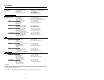
DEPTH OF FIELD AND SYMBOL SPECIFICATION CODE TYPE MINIMUM SMALL ELEMENT MIL. (1/1000) CODE DENSITY DEPTH OF FIELD UPC/EAN 10.4 80% 0" - 5" UPC/EAN 13.0 100% 0" - 6.5" Code 39 7.5 High 0" - 3" Code 39 12.0 Medium 0" - 6" Code 39 21.0 Low 0" - 8" I 2 of 5 7.5 High 0" - 3" I 2 of 5 12.0 Medium 0" - 6" I 2 of 5 21.0 Low 0" - 8" Codabar 6.5 High 0" - 3" Codabar 9.8 Medium 0" - 5" Codabar 13.0 Low 0" - 6.5" Code 93 10.4 80% 0" - 5" Code 93 13.0 100% 0" - 6.
DEPTH OF FIELD AND SYMBOL SPECIFICATION MINIMUM BAR CODE ELEMENT WIDTH A B C D E mm .19 .25 .31 .33 .53 mils 7.
MAINTENANCE Smudges and dirt can interfere with the proper scanning of a bar code. Therefore, the output window will need occasional cleaning. 1. Spray glass cleaner onto lint free, non-abrasive cleaning cloth. 2. Gently wipe the scanner window.
SPECIFICATIONS MS860 AND MS863 SPECIFICATIONS Application: In-Counter Laser Bar Code Scanner Light Source: VLD 650 ± 10 nm Laser Power 0.525 mW (peak) Laser Class UL/CSA/TUV: EMC: CDRH: CLASS IIa; EN60825-1:1994/A11:1996 Class 1 UL Listed, UL 1950; CSA certified, C22.2 No. 950; TUV certified, GS Mark, and EN 60950 FCC, ICES-003 & EN 55022 Class A MECHANICAL Dimensions: Weight: Orientation: 175 mm (6.9")L x 173 mm (6.8")W x 97 mm(3.8")H 2.45 kg (5.4 lbs.
SPECIFICATIONS (CONT.) MS860 AND MS863 SPECIFICATIONS OPERATIONAL Depth of Field: Minimum Bar Width: Scan Speed: Scan Pattern: Exit Angle: Indicators (LED): Beeper Operation: Maintenance: 0 mm - 203 mm (0" - 8"), programmable 0.191 mm (7.
DEFAULT SETTINGS Many function of the scanner can be “ programmed” - that is, enabled or disabled. The scanner is shipped from the factory programmed to a set of default conditions. The default parameter of the scanner has an asterisk (*) in the charts on the following pages. If an asterisk is not in the default column then the default setting is OFF or DISABLED. Every communication does not support every parameter.
DEFAULT SETTINGS (CONT.) PARAMETER DEFAULT OCIA IBM 46XX KEYBOARD RS-232* PARALLEL WEDGE Paraf Support 9 9 9 9 Matrix 2 of 5 9 9 9 9 LIGHT PEN 9 EAN-8 * 9 9 9 9 9 9 EAN-13 * 9 9 9 9 9 9 UPC-E * 9 9 9 9 9 9 UPC-A * 9 9 9 9 9 9 Var.
DEFAULT SETTINGS (CONT.
DEFAULT SETTINGS (CONT.
DEFAULT SETTINGS (CONT.
DEFAULT SETTINGS (CONT.
DEFAULT SETTINGS (CONT.
SCANNER PINOUT CONNECTIONS Version “1” Pin Assignments for RS-232, OCIA and Light Pen Emulation The version “1” scanner head cable is terminated with a male 25-pin D-type connector. Connecting the scanner to the host device may require a communication cable. The communication cable may include a connection for a transformer or it may be designed to draw power directly from the host device. This can be ordered when the scanner is purchased.
SCANNER PINOUT CONNECTIONS Version “2” Pin Assignments for Parallel Communication The version “2” scanner head cable is terminated with a male 25-pin D-type connector. Connecting the scanner to the host device may require a communication cable. The communication cable may include a connection for a transformer or it may be designed to draw power directly from the host device. This can be ordered when the scanner is purchased. The version “2” scanner is designed to be used for Parallel communication.
SCANNER PINOUT CONNECTIONS Version “11” Pin Assignments for RS-485 The version “11” scanner head cable is terminated with a male 25-pin D-type connector. Connecting the scanner to the host device may require a communication cable. The communication cable may include a connection for a transformer or it may be designed to draw power directly from the host device. This can be ordered when the scanner is purchased.
SCANNER PINOUT CONNECTIONS Version “17” Pin Assignments for Keyboard Wedge, RS-232 and Light Pen Emulation The version “17” scanner head cable is terminated with a male 25-pin D-type connector. Connecting the scanner to a PC, requires a communication cable and a transformer. Connecting the communication cable to a PC, may require an adapter cable. The version “17” scanner is designed to be used as a keyboard wedge.
Limited Warranty The MS860 and MS863 scanners are manufactured by Metrologic at its Blackwood, New Jersey, U.S.A. facility. The MS860 and MS863 scanners have a two (2) year limited warranty from the date of manufacture. Metrologic warrants and represents that all MS860 and MS863 scanners are free of all defects in material, workmanship and design, and have been produced and labeled in compliance with all applicable U.S.
NOTICES Notice This equipment has been tested and found to comply with limits for a Class A digital device, pursuant to part 15 of the FCC Rules. These limits are designed to provide reasonable protection against harmful interference when the equipment is operated in a commercial environment. This equipment generates, uses and can radiate radio frequency energy and, if not installed and used in accordance with the instruction manual, may cause harmful interference to radio communications.
NOTICES (CONT.) Attenzione L’utilizzo di sistemi di controllo, di regolazioni o di procedimenti diversi da quelli descritti nel presente Manuale può provocare delle esposizioni a raggi laser rischiose. Il cliente non deve assolutamente tentare di riparare egli stesso lo scanner laser. Non guardate mai il raggio laser, anche se credete che lo scanner non sia attivo. Non aprite mai lo scanner per guardare dentro l’apparecchio. Facendolo potete esporVi ad una esposizione laser rischiosa.
PATENTS Patent Information This METROLOGIC product may be covered by one or more of the following U.S. Patents: U.S. Patent No.
INDEX A I Adapter Cable ............... 1, 6, 10, 38 Application...................................10 Indicators ...................................... 1 LED ................... 1, 13, 15, 16, 27 Installation............................. 11, 39 Interfaces ................................ 4, 38 B Bar codes .......................... 1, 19, 27 Base ..............................................8 Beeper........... 3, 4, 7, 10, 15, 18, 27 keyboard wedge.................. 1, 9, 38 C L Cable ........
INDEX S V ScanSelect .. 1, 2, 4, 7, 9, 14, 19, 38 ScanSet............1, 4, 7, 9, 14-19, 38 Service ........................................39 Specifications ........................26, 27 Stand ................................. 2, 12, 14 Ventilation ................................... 27 Voltage.............................. 3, 10, 26 Volume control card .... 2, 19, 20, 30 T Warranty ..................................... 39 Weight......................................... 26 Window .....................
NOTES
NOTES
August 2002 Printed in the USA 00 - 02202A