METROLOGIC INSTRUMENTS, INC.
Copyright © 2008 by Metrologic Instruments, Inc. All rights reserved. No part of this work may be reproduced, transmitted, or stored in any form or by any means without prior written consent, except by reviewer, who may quote brief passages in a review, or provided for in the Copyright Act of 1976. Trademarks Metrologic is a registered trademark of Metrologic Instruments, Inc.
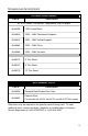
TABLE OF CONTENTS Introduction........................................................................................................... 1 Scanner and Accessories..................................................................................... 2 Installation For OCIA Interface............................................................................................ 4 For Keyboard Wedge Interface.........................................................................
TABLE OF CONTENTS Default Settings .................................................................................................. 40 Scanner and Cable Terminations Scanner Pinout Connections .......................................................................... 46 Cable Connector Configurations (Host End)................................................... 48 Limited Warranty ................................................................................................
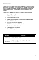
INTRODUCTION The MS7320 InVista® offers an outstanding combination of features, versatility, performance, and durability. This fixed mount laser bar code scanner provides ease of use and high throughput speeds by featuring a large, dynamic, and aggressive scan volume. Firmware updates are easily loaded into Flash memory.
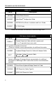
SCANNER AND ACCESSORIES B ASIC K IT Part # Description MS7320 InVista Series Scanner 00-02407 MetroSelect® Configuration Guide 00-02896 MS7320 InVista Series Installation and User’s Guide 52-52511 24" EAS Cable Guides also available for download at www.metrologic.com. O PTIONAL A CCESSORIES Part # 59-59xxx* Description Straight PowerLink Cable with built in power jack. 2.1 m (7') cord with short strain relief xxx* specifies connection to the host.
SCANNER AND ACCESSORIES O PTIONAL A CCESSORIES Part # Description AC to DC Power Transformer - Regulated 5.
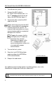
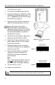
INSTALLATION FOR OCIA INTERFACE 1. Turn off the host system. 2. Connect the MVC cable to the 10-pin OCIA interface jack. It is the 2nd round opening from the left side of the MS7320 (see figure 1). 3. Connect the other end of the MVC cable to the host. Before continuing verify that the MVC cable is connected to the appropriate interface jack on the scanner. An incorrect cable connection can cause communication problems or potential damage to the scanner.
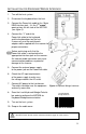
INSTALLATION FOR KEYBOARD WEDGE INTERFACE 1. Turn off the host system. 2. Disconnect the keyboard from the host. 3. Connect the PowerLink cable to the 10-pin nd KBW interface jack. It is the 2 round opening from the left side of the MS7320 (see figure 2). 4. Connect the “Y” end of the PowerLink cable to the keyboard and the keyboard port on the host. If necessary use the male/female adapter cable supplied with the scanner for proper connections.
INSTALLATION FOR STAND-ALONE KEYBOARD INTERFACE 1. Turn off the host system. 2. Disconnect the keyboard from the host. 3. Connect the PowerLink cable to the 10-pin Stand-Alone Keyboard interface jack. It is the 2nd round opening from the left side of the MS7320 (see figure 3). 4. Connect the other end of the PowerLink cable to the keyboard port on the host. Before continuing verify that the PowerLink cable is connected to the appropriate interface jack on the scanner.
INSTALLATION FOR USB INTERFACE 1. Turn off the host system. 2. Determine if your application requires USB Keyboard communication protocols or USB Point-of-Sale communication protocols. 3. If you require USB Keyboard communication protocols, skip to step 4. If you require USB Point-of-Sale communication protocols set the dip switches shown in figure 4a to positions 1 and 2. 4. Connect the PowerLink cable to the 10-pin nd USB interface jack.
INSTALLATION FOR RS232 OR LIGHT PEN INTERFACES 1. Turn off the host system. 2. Connect the PowerLink cable to the 10-pin RS232/Light Pen interface jack. It is the 1st round opening from the left side of the MS7320 (see figure 5). 3. Connect the other end of the PowerLink cable to the host. Before continuing verify that the PowerLink cable is connected to the appropriate interface jack on the scanner. An incorrect cable connection can cause communication problems or potential damage to the scanner. 4.
INSTALLATION FOR RS232 OR LIGHT PEN INTERFACES Codes needed for Step 7 on page 8.
INSTALLATION FOR IBM 46XX INTERFACE 1. Turn off the host system. 2. Connect the MVC cable to the 10-pin IBM 46xx interface jack. It is the 1st round opening from the left side of the MS7320 (see figure 6). 3. Connect the other end of the MVC cable to the host. Before continuing verify that the MVC cable is connected to the proper communication jack on the scanner. Incorrect cable connection can cause communication problems or potential damage to the scanner.
INSTALLATION OF A SECONDARY SCANNER 1. Turn off the host system. 2. Connect the round end of the PowerLink RS232 AUX cable [ MLPN 54-54667 ] to the RS232 jack of the auxiliary scanner (see figure 7). 3. Connect the other end of the PowerLink RS232 AUX cable into the 1st jack from the left side of the MS7320. The Aux jack has a square opening. The following Metrologic scanners can be used in the “Aux” input of the MS7320: the MS9520, MS9540, MS6220, MS7120, MS6520, MS6720, MS7220 or another MS7320.
INSTALLATION OF A SECONDARY SCANNER 11. Scan the following bar code to configure the auxiliary port on the MS7320 to accept a Metrologic scanner as the secondary scanner. The following bar codes do not apply when using an MS6720 as a secondary scanner. Contact a Metrologic representative for additional information on the MS6720. If the secondary scanner is not a Metrologic scanner refer to Section O of the MetroSelect Configuration Guide.
INSTALLATION OF A SECONDARY SCANNER Figure 7: Connector Orientation (Top) Auxiliary Scanner Setup (Bottom) 13
SCANNER PARTS Figure 8: Scanner Parts Output Window (Laser Aperture) Speaker Replaceable Window Face Plate Red LED (Top LED) Green LED (Bottom LED) Multi-Function Button (see page 21) Cable Connection and Dip Switch Area Cable Cover Pedestal Base/Stand Foot MAINTENANCE Smudges and dirt on the unit’s window can interfere with the unit’s performance. If the glass window requires cleaning, use only a mild glass cleaner containing no ammonia.
CABLE COVER INSTALLATION AND REMOVAL Figure 9: Installing the Cable Cover (left). Removing the Cable Cover (bottom right).
SCANNER LABELS The MS7320 has 2 labels on the back of the unit. These labels contain the model number, date of manufacture, serial number, and caution information. An additional caution label is located under the window faceplate and a label noting the jack interfaces is located under the connector cover. The following are examples of these labels.
AUDIBLE INDICATORS When the MS7320 scanner is in operation, it provides audible feedback. These sounds indicate the status of the scanner. Eight settings are available for the tone of the beep (normal, 6 alternate tones and no tone). To change the tone, use the Multi-Function Button or refer to the MetroSelect Configuration Guide. One Beep When the scanner first receives power, the green LED will turn on, the red LED will flash and the scanner will beep once.
VISUAL INDICATORS There is a red LED and green LED on the front of the MS7320. When the scanner is on, the flashing or constant illumination of the LEDs indicates the status of the current scan and the scanner. Figure 12: LEDs No Red or Green LED The LEDs will not be illuminated if the scanner is not receiving power from the host or transformer. Steady Green When the laser is active, the green LED is illuminated. The green LED will remain illuminated until the laser is deactivated.
FAILURE MODES Figure 13: LEDs Flashing Green and One Razzberry Tone This indicates the scanner has experienced a laser subsystem failure. Return the unit for repair at an authorized service center. Flashing Red and Green and Two Razzberry Tones This indicates the scanner has experienced a motor failure. Return the unit for repair at an authorized service center.
POWER SAVE MODES AND THE MULTI-FUNCTION BUTTON The MS7320 has five configurable power save modes. Refer to the MetroSelect Configuration Guide for additional information on Power Save Modes. 1. Blink Power Save Mode (Default): “Blinks” the laser OFF & ON after a configured period of non-use. When the scanner recognizes a bar code it will exit the Blink mode. 2. Laser Off Power Save Mode: Turns the laser OFF after a configured period of non-use.
POWER SAVE MODES AND THE MULTI-FUNCTION BUTTON Figure 14: The Multi-Function Button CHANGING THE BEEPER TONE A Short (<3 second) depression and the beeper tone will change. The new tone will be heard, followed by a short pause. Then two more of the new tones will be heard signifying the new setting has been stored in memory. The silent (no beep) tone is also selectable.
SCAN VOLUME (BASED ON 100% UPC BAR CODES) Figure 18: Scan Area Top View (top) Side View (Bottom) Specifications are subject to change without notice.
DEPTH OF FIELD BY MINIMUM BAR CODE ELEMENT WIDTH (BASED ON 100% UPC BAR CODES) Figure 19: Depth of Field Top View Minimum Bar Code Element Width mm mils A .13 5.2 B .19 7.5 C .26 10.4 D .33 13 E .48 19 Specifications are subject to change without notice.
DEPTH OF FIELD BY MINIMUM BAR CODE ELEMENT WIDTH (BASED ON 100% UPC BAR CODES) Figure 20: Depth of Field Side View Minimum Bar Code Element Width mm mils A .13 5.2 B .19 7.5 C .26 10.4 Specifications are subject to change without notice. 24 D .33 13 E .
FLEX STAND INSTALLATION Flex Stand (Optional), Kit Components a. Stand Base Cover ..................Qty. 1 b. Stand Base ............................Qty. 1 c. Small Flex Cover* ..................Qty. 1 d. Flex Pole*...............................Qty. 1 e. Large Flex Cover* ..................Qty. 1 f. #8 x 1.00" Wood Screw..........Qty. 4 g. ¼"-20 x ¾" Flat Head Screw ..Qty. 1 h. ¼" External Lock Washer.......Qty. 2 i. ¼" Flat Washer .....................Qty.
FLEX STAND INSTALLATION 2. Secure the base plate to the counter and attach the flex pole assembly. Slide the flex cover(s)* over the flex pole assembly. Figure 23: Pole Assembly 3. Figure 24: Cover Assembly Remove the scanner’s cable cover if it was previously installed. Figure 25: Cable Cover Removal 4. Pull the tab on the scanner’s pedestal to release the lock. Slide the pedestal off the scanner.
FLEX STAND INSTALLATION 5. Attach the scanner pedestal to the flex pole. Figure 27: Attach Pedestal to Pole 6. Slide the scanner onto the pedestal until it clicks locking the scanner to the stand. Figure 28: Install Pedestal to Scanner 7. Before installing the scanner’s cable cover, refer to pages 4-13 for instructions on the proper cable connections. 8. Install the scanner’s cable cover.
EAS DEACTIVATION ANTENNA SW1 and SW2 are the switch banks inside the Checkpoint Device that set the deactivation range. Metrologic recommends end users program the MS7320 to the Fixed for Low Density Codes - Depth of Field*, so that the unit does not scan out beyond the deactivation range.
TROUBLESHOOTING GUIDE The following guide is for reference purposes only. Contact a Metrologic representative at 1-800-ID-METRO or 1-800-436-3876 to preserve the limited warranty terms. MS7320 SERIES TROUBLESHOOTING GUIDE SYMPTOMS POSSIBLE CAUSE(S) SOLUTION All Interfaces No LEDs, beep or motor spin. No power is being supplied to the scanner. Check transformer, outlet and power strip. Make sure the cable is plugged into the scanner. No LEDs, beep. No power is being supplied to the scanner from host.
TROUBLESHOOTING GUIDE SYMPTOMS POSSIBLE CAUSE(S) SOLUTION Scanning a particular symbology that is not enabled. UPC/EAN, Code 39, interleaved 2 of 5, Code 93, Code 128 and Codabar are enabled by default. Verify that the type of bar code being read has been selected. The scanner has been configured for a character length lock, or a minimum length and bar code being scanned does not satisfy the configured criteria. Verify that the bar code that is being scanned falls into the criteria.
TROUBLESHOOTING GUIDE SYMPTOMS Scanner beeps at some bar codes and NOT for others of the same bar code symbology. Multi-Function Button is not working. POSSIBLE CAUSE(S) SOLUTION The bar code may have been printed incorrectly. Check if it is a check digit/character/or border problem. The scanner is not configured correctly for this type of bar code. Check if check digits are set properly. The minimum symbol length setting does not work with the bar code.
TROUBLESHOOTING GUIDE SYMPTOMS POSSIBLE CAUSE(S) SOLUTION Everything works except for a couple of characters. These characters may not be supported by that country’s key look up table. Try operating the scanner in Alt mode. The unit is transmitting each character. Configuration is not correct. Increase the interscan code delay setting. Adjust whether the F0 break is transmitted. It may be necessary to try this in both settings. Alpha characters show as lower case. Computer is in Caps Lock mode.
TROUBLESHOOTING GUIDE SYMPTOMS POSSIBLE CAUSE(S) The host is The scanner and host receiving data but may not be configured the data does not for the same interface. look correct. Intercharacter delay needs to be added to the transmitted output. Characters are being dropped. SOLUTION Check that the scanner and the host are configured for the same interface. Add some intercharacter delay to the transmitted output by using the MetroSelect Configuration Guide (MLPN 00-02407).
DESIGN SPECIFICATIONS MS7320 SERIES DESIGN SPECIFICATIONS OPERATIONAL Light Source: Visible Laser Diode (VLD) @ 650 nm Laser Power: 0.678 mW (peak) Depth of Field: Width of Scan Field: Scan Speed: Scan Pattern: Scan Lines: Min Bar Width: 0 mm to 215 mm (0"- 8.5") for 0.33 mm (13 mil) bar code 38 mm (1.5") @ 15 mm (0.6"); 135 mm (5.3") @ 191 mm (7.5") 2000 scans/second 5 fields of 4 parallel lines (omnidirectional) 20 0.127 mm (5.
DESIGN SPECIFICATIONS MS7320 SERIES DESIGN SPECIFICATIONS ELECTRICAL Input Voltage: Power: Operating Current: DC Transformers: 5.2VDC ± 0.25V 1.9 W 360 mA Class II; 5.2 VDC @ 1A For Regulatory Compliance Information refer to pages 51 -54.
RS232 DEMONSTRATION PROGRAM If an RS232 scanner is not communicating with your IBM compatible PC, key in the following BASIC program to test that the communication port and scanner are working. This program is for demonstration purposes only. It is only intended to prove that cabling is correct, the com port is working, and the scanner is working. If the bar code data displays on the screen while using this program, it only demonstrates that the hardware interface and scanner are working.
APPLICATIONS AND PROTOCOLS The model number on each scanner includes the scanner number and factory default communications protocol. VERSION IDENTIFIER SCANNER COMMUNICATION PROTOCOL(S) 13 RS232, IBM 46xx, OCIA, Aux 37 RS232, Light Pen, Keyboard Wedge, Stand-Alone Keyboard, USB, Aux 7320 The MS7320 with Built-in PC Keyboard Wedge Interface is designed to be used for keyboard emulation only.
CONFIGURATION MODES The MS7320 has three modes of configuration. • Bar Codes The MS7320 can be configured by scanning the bar codes included in the Metrologic Configuration Guide shipped with the area imager. This manual can also be downloaded FREE from Metrologic’s website (www.metrologic.com). • MetroSet2 This user-friendly Windows-based configuration program allows you to simply ‘point-and-click’ at the desired scanner options. This program can be downloaded for FREE from Metrologic’ website (www.
UPGRADING THE FIRMWARE The MS7320 is part of Metrologic's line of scanners with flash upgradeable firmware. The upgrade process requires, a new firmware file supplied to the customer by a customer service representative and Metrologic's MetroSet2 software . A personal computer running Windows 95 or greater with an available RS232 serial or USB port is required to complete the upgrade. Do not use the standard cable supplied with Keyboard Wedge or RS485 MS7320 interface kits for firmware upgrades.
DEFAULT SETTINGS Many functions of the scanner can be "configured" - that is, enabled or disabled. The scanner is shipped from the factory configured to a set of default conditions. The default parameter of the scanner has an asterisk ( * ) in the charts on the following pages. If an asterisk is not in the default column then the default setting is Off or Disabled. Every communication does not support every parameter.
DEFAULT SETTINGS PARAMETER DEFAULT OCIA RS232 LIGHT PEN IBM 46XX KBW USB Spaces High as Code 39 Bars High as Scanned Spaces High as Scanned DTS/SIEMENS DTS/NIXDORF * NCR F NCR S Poll Light Pen Source Beeper Tone Normal Beep/Transmit Sequence Before Transmit Beeper Volume Loudest CommunicationTimeout None Razzberry Tone on Timeout Three Beeps on Timeout No Beeps on Timeout * Enter Power Save Mode 10 mins.
DEFAULT SETTINGS PARAMETER DEFAULT Same Symbol Rescan Timeout: 2000 msecs Intercharacter Delay Configurable in 1 msec steps (MAX 255 msecs) 1 msecs 10 msecs in KBW Number of Scan Buffers 1 Transmit EAN-8 Check Digit * Transmit EAN-13 Check Digit * Transmit UPC-A Check Digit * Transmit UPC-E Check Digit Expand UPC-E Convert UPC-A to EAN-13 UPC GTIN-14 Format Transmit Lead Zero on UPC-E Convert EAN-8 to EAN-13 Transmit UPC-A Number System * Transmit UPC-A Manufacturer ID# * Transmit UPC-A Item
DEFAULT SETTINGS PARAMETER DEFAULT OCIA RS232 LIGHT PEN IBM 46XX KBW USB 8 Data Bits 7 Data Bits * Transmit Sanyo ID Characters Nixdorf ID LRC Enabled UPC Prefix UPC Suffix Transmit AIM ID Characters STX Prefix ETX Suffix Carriage Return * Line Feed - disabled by default in KBW * Tab Prefix Tab Suffix "DE" Disable Command "FL" Laser Enable Command DTR Handshaking Support RTS/CTS Handshaking Character RTS/CTS * Message RTS/CTS XON/XOFF Handshaking ACK/NAK Two Digit Supplements as code 39 Fi
DEFAULT SETTINGS PARAMETER DEFAULT OCIA RS232 LIGHT PEN Bookland 977 (2 digit) Supplemental Requirement Supplements are not Required * Two Digit Redundancy * Five Digit Redundancy 100 msec to Find Supplement Configurable in 100 msec steps (MAX 800 msec) * as code 39 Coupon Code 128 Configurable Code Lengths 7 avail. Configurable Prefix Characters 10 avail.
DEFAULT SETTINGS Default settings for “Aux” interface The secondary scanner and the MS7320 always communicate via RS232. Data is relayed to the host via various primary interfaces.
SCANNER AND CABLE TERMINATIONS Scanner Pinout Connections The MS7320 scanner interfaces terminate to 10-pin modular jacks located on the back of the unit. The serial number label indicates the model number of the scanner.
SCANNER AND CABLE TERMINATIONS Figure 32: Scanner Interface Ports MS732x-37 Keyboard Wedge, StandAlone Keyboard or USB Pin 1 2 3 4 5 6 7 8 9 10 Function Ground USB DUSB D+ PC Data PC Clock KB Clock PC +5V, V-USB KB Data +5VDC Shield Ground MS732x-37 RS232 or Light Pen Pin 1 2 3 4 5 6 7 8 9 10 Function Ground RS232 Transmit Output RS232 Receive Input RTS Output CTS Input DTR Input/LTPN Source N/C LTPN Data +5VDC Shield Ground MS732x-13/-37 Auxiliary Port RS232 IN Only Pin 1 2 3 4 5 6-10 Function Groun
SCANNER AND CABLE TERMINATIONS Cable Connector Configurations (Host End) PowerLink Cable MLPN 59-59xxx* Pin 1 2 3 4 5 6 7 8 9 Function Shield Ground RS232 Transmit Output RS232 Receive Input DTR Input Power/Signal Ground Reserved CTS Input RTS Output +5VDC 9 5 6 1 9-Pin D-Type Conn.
SCANNER AND CABLE TERMINATIONS Cable Connector Configurations (Host End) PowerLink, Keyboard Wedge MLPN 59-59002 Pin 1 Function Keyboard Clock 2 Keyboard Data 3 No Connect 4 Power Ground 5 Pin 1 +5 Volts DC Function Keyboard Data 2 No Connect 3 Power Ground 4 5 6 +5 Volts DC PC Clock No Connect 5-Pin DIN, Female 6-Pin DIN, Male Metrologic will supply an adapter cable with a 5-pin DIN male connector on one end and a 6-pin mini DIN female connector on the other.
LIMITED WARRANTY ® The MS7320 InVista Series scanners are manufactured by Metrologic at its Blackwood, New Jersey, U.S.A. facility. The MS7320 Series scanners have a three (3) year or two (2) year limited warranty from the date of manufacture. The duration of the warranty is dependent upon the country where the product was purchased. Please contact your Metrologic representative for warranty information.
REGULATORY COMPLIANCE SAFETY ITE Equipment IEC 60950-1; EN 60950-1 Laser Laser Class 1: IEC 60825-1:1993+A1+A2, EN: 60825-1:1994+A1+A2 Caution Use of controls or adjustments or performance of procedures other than those specified herein may result in hazardous laser light exposure. Under no circumstances should the customer attempt to service the laser scanner. Never attempt to look at the laser beam, even if the scanner appears to be nonfunctional.
REGULATORY COMPLIANCE SAFETY Achtung Die Verwendung anderer als der hier beschriebenen Steuerungen, Einstellungen oder Verfahren kann eine gefährliche Laserstrahlung hervorrufen. Der Kunde sollte unter keinen Umständen versuchen, den Laser-Scanner selbst zu warten. Sehen Sie niemals in den Laserstrahl, selbst wenn Sie glauben, daß der Scanner nicht aktiv ist. Öffnen Sie niemals den Scanner, um in das Gerät hineinzusehen. Wenn Sie dies tun, können Sie sich einer gefährlichen Laserstrahlung aussetzen.
REGULATORY COMPLIANCE EMC Class A Devices (Continued…) This device complies with part 15 of the FCC Rules. Operation is subject to the following two conditions: (1) This device may not cause harmful interference, and (2) this device must accept any interference received, including interference that may cause undesired operation. Notice This Class A digital apparatus complies with Canadian ICES-003. Remarque Cet appareil numérique de la classe A, conformé a la norme NMB-003 du Canada.
REGULATORY COMPLIANCE EMC Changes or modifications not expressly approved by the party responsible for compliance could void the user’s authority to operate the equipment. Class B Devices The following is applicable when the scanner cable is less than 3 meters (9.8 feet) in length when fully extended: Les instructions ci-dessous s’appliquent aux cables de scanner ne dépassant pas 3 métres (9.
PATENTS This METROLOGIC product may be covered by, but is not limited to, one or more of the following U.S. Patents: U.S. Patent No.
INDEX A F Accessories ...................................2 Adapter........................................49 Auxiliary................. 2, 33, 45, 47, 48 Scanner ....................... 11, 12, 13 Face Plate................................... 15 Firmware ..................................... 39 Flash ROM.................................. 39 B Bar Code .....................................38 Beep .............. 17–19, 29–33, 39, 41 Button ........................ 14, 20, 21, 39 C Cable ..................
INDEX M RS232 ........9, 32, 36, 40–45, 47, 48 Maintenance................................14 Manual.....................................2, 37 MetroSelect .................................38 MetroSet2....................................39 Min Bar Width..............................34 Multi-Function Button....... 14, 20, 21 MVC ..............................................2 S N Notices ............................ 51, 53, 54 O OCIA ........................... 4, 40–45, 46 Operating Current...............
58
January 2008 Printed in the USA 0 0 - 0 2 8 9 6G