LOCATIONS CORPORATE HEADQUARTERS North America Metrologic Instruments, Inc. 90 Coles Road Blackwood, NJ 08012-4683 Customer Service: 1-800-ID-METRO Tel: 856-228-8100 Fax: 856-228-6673 Email: info@metrologic.com Internet: www.metrologic.com Metrologic Instruments GmbH Dornierstrasse 2 82178 Puchheim b. Munich, Germany Tel: +49 (0) 89 89019 0 Fax: +49 (0) 89 89019 200 Email: info@europe.metrologic.
TABLE OF CONTENTS Introduction........................................................................................................... 1 Accessories and Supplies .................................................................................... 2 Quick Start............................................................................................................ 3 Standard Scanner Installation ..............................................................................
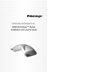
INTRODUCTION The MS5145 Eclipse is a single-line, hand-held laser scanner. Equipped with Metrologic’s patented CodeGate technology, Eclipse can be used in a wide variety of applications. CodeGate technology allows the user to easily target the desired bar code and complete the data transmission with a simple press of a button. This combination makes Eclipse a perfect selection for menu scanning, point-of-sale, document processing and inventory control.
ACCESSORIES AND SUPPLIES The following is a list of parts that may or may not be included in the MS5145 kit. • Eclipse MS5145 Single-Line Laser Scanner • AC to DC Power Transformer – Regulated 5.2VDC @ 650 mA output • • One of the following may be included: • 120 V United States [ MLPN 45-45593 ] • 220 V - 240 V Continental European [ MLPN 45-45591 ] • 220 V – 240 V United Kingdom [ MLPN 45-45592 ] PowerLink Cable • One of the following may be included: • RS232 Cable: 2.
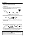
QUICK START 1. Connect the 10-pin RJ45 plug into the jack on the Eclipse MS5145. You will hear a ‘click’ when the connection is made. 2. Connect the L-shaped plug of the power supply into the power jack on the PowerLink cable. 3. Connect the power supply into an AC outlet. Make sure the AC input requirements of the power supply match the AC outlet. (See caution statement below) p n 4.
STANDARD RS232 SCANNER INSTALLATION 1. Turn off the host system. 2. Connect the 10-pin RJ45 plug of the PowerLink cable into the jack on the MS5145 RS232 scanner. Note: If the MS5145 is receiving power from the host system, skip to step #5. (See caution statement below*) 3. Connect the L-shaped plug of the power supply into the power jack on the PowerLink cable. (See caution statement below**) 4. Make sure the AC input requirements of the power supply match the AC outlet.
KEYBOARD WEDGE SCANNER INSTALLATION 1. Turn off the host system. 2. Connect the 10-pin RJ45 plug of the PowerLink cable into the jack on the MS5145. 3. Disconnect the keyboard from the host system. 4. Connect the L-shaped plug of the power supply into the power jack on the PowerLink cable (refer to the manufacturer’s recommendation and Note on page 6). 5. Make sure the AC input requirements of the power supply match the AC outlet.
KEYBOARD WEDGE INSTALLATION (CONTINUED) Manufacturer’s Recommendation If the keyboard port of the host system cannot supply enough current, the use of an external power supply with the MS5145 Keyboard Wedge will be necessary. Powering the MS5145 directly from the computer keyboard connector could interfere with the operation of the scanner or the computer.
USB SCANNER INSTALLATION 1. Connect the 10-pin RJ45 plug of the PowerLink cable into the jack on the MS5145 USB scanner. Note: The MS5145 USB scanner will receive power directly from the host system; no external power supply is required. 2. Connect the USB connector of the PowerLink cable into the USB port of the host system. n 3. o When the MS5145 is ready to scan, the green LED will turn on, the red LED will flash and the scanner will beep once.
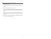
DISCONNECTING THE POWERLINK CABLE FROM THE SCANNER Before removing the cable from the scanner, Metrologic recommends that the power on the host system is off and the power supply has been disconnected from the PowerLink cable. o& p q n 1. Locate the small ‘pin-hole’ on the back of the scanner. 2. Bend an ordinary paperclip into the shape shown above. 3. Insert the paperclip (or other small metallic pin) into the small ‘pin-hole’. 4. You will hear a faint ‘click’.
SCANNER PARTS 1. Green & Red LEDs The MS5145’s laser pulses on and off when no bar code is presented, and stays on when it senses a bar code. The green LED remains on during normal pulse and scanning operation, and it blinks during power save mode. On a successful read of a bar code, the red LED will flash and the scanner will beep once. The LEDs are also used as diagnostic indicators and mode indicators. 2. Output Window Laser Light emits from this aperture. 3.
AUDIBLE INDICATORS When the MS5145 scanner is operational, it provides audible feedback. These sounds indicate the status of the scanner. Eight settings are available for the tone of the beep (normal, 6 alternate tones and no tone). To change the tone, refer to the Configuration Guide. One Beep – on power up The green LED will turn on, then the red LED will flash and the scanner will beep once. The red LED will remain on for the duration of the beep. The scanner is now ready to scan.
VISUAL INDICATORS There is a red LED and a green LED on the MS5145. When the scanner is on, the activity of the LEDs indicates the status of the current scan and the scanner. Green and Red LEDs are off The LEDs will not be illuminated if the scanner is not receiving power from the host or transformer. Steady Green Indicates normal pulse or continuous laser operation. Accompanied by a razzberry tone, it indicates that an invalid bar code has been scanned.
FAILURE MODES One Razzberry Tone on Power-up This indicates the scanner has experienced a laser or flipper subsystem failure. Return the unit for repair to a Metrologic Authorized Service Center. Continuous Razzberry Tone with all LEDs off If, upon power up, the scanner emits a continuous razzberry tone, then the scanner has an experienced an electronic failure. Return the unit for repair to a Metrologic Authorized Service Center.
SCAN AREA Minimum Bar Code Element Width A B C D E F mm .10 .12 .17 .26 .33 .66 mils 4.1 4.8 6.8 10.
LABELS Each scanner has one label on the underside of the unit. This label has the model number, date of manufacture, serial number, laser and caution information. The following is an example of this label. Patent Information-See Manual FCC and ICES-003 Information-See Manual Warranty VOID if case opened. Contains no user serviceable components. Complies with 21 CFR 1040.10 & 1040.
TROUBLESHOOTING GUIDE The following guide is for reference purposes only. Contact a Metrologic representative to preserve the limited warranty terms on page 31. SYMPTOMS POSSIBLE CAUSE(S) SOLUTION No power is being supplied to the scanner Check transformer, outlet and power strip. Make sure the cable is plugged into the scanner. No power is being supplied to the scanner from host Some host systems cannot supply enough current to power the MS5145. Use the proper power supply.
TROUBLESHOOTING GUIDE (CONTINUED) SYMPTOMS POSSIBLE CAUSE(S) SOLUTION The unit powers up, but does not scan Scanning a particular symbology that is not enabled UPC/EAN, Code 39, Interleaved 2 of 5, Code 93, Code 128 and Codabar are enabled by default. Verify that the type of bar code being read has been selected.
TROUBLESHOOTING GUIDE (CONTINUED) SYMPTOMS POSSIBLE CAUSE(S) SOLUTION Scanner beeps at some bar codes and NOT for others of the same bar code symbology The bar code may have been printed incorrectly Check if it is a check digit/character/or border problem. Scanner beeps at some bar codes and NOT for others of the same bar code symbology The scanner is not configured correctly for this type of bar code Check if check digits are set properly.
TROUBLESHOOTING GUIDE (CONTINUED) SYMPTOMS The unit is not transmitting each character (Keyboard Wedge) POSSIBLE CAUSE(S) SOLUTION Configuration is not correct Increase interscan code delay setting. Adjust whether the F0 break is transmitted. It may be necessary to try this in both settings. Alpha characters show as lower case (Keyboard Wedge) Computer is in Caps Lock mode Enable Caps Lock detect setting of the scanner to detect whether the PC is operating in Caps Lock.
RS-232 DEMONSTRATION PROGRAM If an RS-232 scanner is not communicating with your IBM compatible PC, key in the following BASIC program to test that the communication port and scanner are working. This program is for demonstration purposes only. It is only intended to prove that cabling is correct, the communication port is working, and the scanner is working. If the bar code data displays on the screen while using this program, it only demonstrates that the hardware interface and scanner are working.
APPENDIX A Specifications OPERATIONAL Light Source Visible Laser Diode 650 nm ± 10 nm Laser Power (peak) <1.0 mW Depth of Scan Field (for 13mil at Default) 0 mm – 140 mm (0” – 5.5”) Scan Speed 72 ± 2 scan lines per second Scan Pattern Single scan line Minimum Bar Width 0.102 mm (4.
APPENDIX A (CONTINUED) ELECTRICAL Input Voltage 5 VDC ± 0.25 V Power - Operating 0.675 mW Current - Operating 135 mA peak @ 5 VDC DC Transformers Class 2; 5.2 V @ 650 mA UL UL listed for US and Canada; UL 60950, C22.2 No.
APPENDIX B Default Settings Many functions of the scanner can be “programmed” – that is, enabled or disabled. The scanner is shipped from the factory programmed to a set of default conditions. The default parameter of the scanner has an asterisk (*) in the charts on the following pages. If an asterisk is not in the default column then the default setting is OFF or DISABLED. Every communication does not support every parameter.
APPENDIX B (CONTINUED) Parameter Default Bars High as Code 39 Spaces High as Code 39 Bars High as Scanned Spaces High as Scanned Low Speed Option Toggle on Decode 10x Narrow Element 50x Narrow Element Poll Light Pen Source Beeper Tone Beep/Transmit Sequence Communication Timeout Razzberry tone on Timeout Three beeps on Timeout Same symbol rescan timeout 100 msecs Same symbol rescan timeout 200 msecs Same symbol rescan timeout 500 msecs Same symbol rescan timeout 1200 msecs Same symbol rescan timeout 2000
APPENDIX B (CONTINUED) Parameter Default OCIA RS232 Light Pen IBM 46XX KBW Inter-character delay Programmable in 1 msec steps (max 255 msecs) 1 msecs 10 msecs in KBW 9 9 9 9 9 * 9 9 9 9 9 9 9 9 9 9 9 9 9 9 9 9 9 9 9 9 9 9 9 9 9 9 9 9 9 9 * 9 9 9 9 9 * 9 9 9 9 9 * 9 9 9 9 9 9 9 9 9 9 9 9 9 9 9 9 9 9 9 9 9 9 9 9 9 9 9 9 9 Transmit UPC-A check digit Transmit UPC-E check digit Expand UPC-E Convert UPC-A to EAN-13 Transmit lead zero on UPC-E
APPENDIX B (CONTINUED) Parameter Carriage Return Line Feed-Disabled by default in KBW Tab Prefix Tab Suffix “C” prefix “I” prefix STX prefix ETX suffix “DE” Disable Command “FL” Laser Commands DTR Handshaking support RTS/CTS Handshaking Character RTS/CTS Message RTS/CTS XON/XOFF Handshaking ACK/NAK Two Digit Supplements Five Digit Supplements Bookland (978) 977 (2 digit) Supplemental Requirement Supplements are not Required Default OCIA RS232 Light Pen IBM 46XX KBW USB 9 9 * 9 * 9 9 9 9 9 9 9
APPENDIX B (CONTINUED) Parameter Coupon Code 128 Programmable Code Lengths Programmable Suffix Characters Prefixes for Individual Code types Inter Scan-Code Delay Programmable (100 µsec steps) Function/Control Key Support Minimum Element Width Programmable in 5.6 µsec steps Country Coded Keyboards 26 Default 7 avail 10 avail OCIA RS232 Light Pen IBM 46XX KBW USB 9 9 As Code 39 9 9 9 9 9 9 9 9 9 9 9 9 9 9 9 800 µsec 1 msec.
APPENDIX C Scanner Pinout Connections MS5145-41 (RS-232C & LTPN) Pin 1 2 3 Function Ground RS-232 Transmit Output RS-232 Receive Input 27
APPENDIX C (CONTINUED) MS5145-37 (USB/KBW) Pin 1 2 3 4 5 6 7 8 9 10 Function Ground DD+ PC DATA PC CLOCK KB CLOCK PC+5V/V_USB KB DATA V_EXT Shield Ground Cable Connector Configurations • RS232 PowerLink Cable with built in power jack [ MLPN 55-55000A ] The RS232 PowerLink cable is terminated with a 9-pin D-Type connector to the host.
APPENDIX C (CONTINUED) • Keyboard Wedge PowerLink and Adapter Cable [MLPN 55-55002A] The Keyboard Wedge PowerLink cable is a “Y” cable terminated with a 5-pin DIN female connector on one end, and a 6-pin mini DIN male on the other. 4 2 5 1 2 3 1 4 3 6 5 Keyboard Wedge PowerLink Cable 5-Pin DIN, Female 6-Pin DIN, Male Metrologic will supply an adapter cable with a 5-pin DIN male connector on one end and a 6-pin mini DIN female connector on the other.
APPENDIX C (CONTINUED) • USB PowerLink cable [ MLPN 55-55165A ] The USB PowerLink cable is terminated with an USB A type connector.
APPENDIX D Warranty and Disclaimer Limited Warranty The MS5145 scanner is manufactured by Metrologic at its Suzhou, China facility. The MS5145 scanners have a two (2) year limited warranty from the date of manufacture. Metrologic warrants and represents that all MS5100 scanners are free of all defects in material, workmanship and design, and have been produced and labeled in compliance with all applicable U.S.
APPENDIX E Notice This equipment has been tested and found to comply with the limits for a Class B digital device, pursuant to Part 15 of the FCC rules. These limits are designed to provide reasonable protection against harmful interference in a residential installation. This equipment generates, uses and can radiate radio frequency and, if not installed and used in accordance with the instruction, may cause harmful interference to radio communications.
APPENDIX F Patent Information “This METROLOGIC product may be covered by one or more of the following U.S. Patents: U.S. Patent No.
INDEX A F AC input/outlet...................2, 3, 4, 6 Accessories ...................................2 Approvals ........................ 13, 20, 30 Assignments pin ...................... 2, 4, 6, 7, 26, 27 Audible ..............................9, 11, 19 Autodiscriminates ........................19 Failure indicator(s) ............ 9, 11, 14 Failure modes ............................. 11 B Bar code ...1, 3, 8-10, 15, 16, 18, 19 Bar width .....................................12 Beep ......
INDEX P Specifications.............................. 19 Parts ..........................................2, 8 Power supply............... 3, 4, 6, 7, 26 Programming modes ......... 3, 17, 18 T Q Quick start .....................................3 R Razzberry tone ............ 9, 10, 11, 22 Red LED.................. 3, 4, 6, 8, 9, 10 Repair....................................11, 28 RMA ............................................28 RS-232 ............ 1, 17, 18, 19, 21, 26 S Scan lines..................
June 2002 70 - 79001B