Copyright © 2006 by Metrologic Instruments, Inc. All rights reserved. No part of this work may be reproduced, transmitted, or stored in any form or by any means without prior written consent, except by reviewer, who may quote brief passages in a review, or provided for in the Copyright Act of 1976. Products and brand names mentioned in this document are trademarks of their respective companies.
TABLE OF CONTENTS Introduction Product Overview ............................................................................................. 1 Scanner and Accessories................................................................................. 2 Scanner Components....................................................................................... 4 Caution and Serial Number Labels................................................................... 5 Stand Specifications ..............................
TABLE OF CONTENTS IR Activation Range Normal........................................................................................................ 22 Reduced ..................................................................................................... 22 Troubleshooting Guide ....................................................................................... 23 Design Specifications .........................................................................................
INTRODUCTION The Fusion is a hand-held, omnidirectional bar code scanner with optional single-line scanning capabilities. It utilizes the powerful Metrologic QuantumE scan engine to provide an outstanding scan performance on all standard 1D barcode symbologies, including RSS.
INTRODUCTION Scanner and Accessories BASIC KIT COMPONENTS Part No. Description MS3780 Fusion Scanner 00-02099 MS3780 Installation and User’s Guide * 00-02407 MetroSelect® Configuration Guide * * Guides also available for download at www.metrologic.com. OPTIONAL ACCESSORIES Part No. Description AC to DC Power Transformer - Regulated 5.2VDC @ 650 mA output.
INTRODUCTION Scanner and Accessories OPTIONAL ACCESSORIES Part No. 53-53213x-N-3 Description USB Full Speed Cable, Locking Plus-Power™Type A 3 m (10 ft.) straight cord, short strain relief USB Full Speed Cable, Locking Plus-Power™Type A 5 m (17 ft.) straight cord, short strain relief 53-53214x-N-3 This cable is for use with full speed USB (-40) interface only. 53-53235x-N-3 USB Low Speed Communication Cable, Type A (Non-Locking) Connector 2.8 m (9.2 ft.
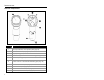
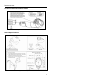
INTRODUCTION Scanner Components Figure 1. Scanner Components ITEM NO.
INTRODUCTION Caution and Serial Number Labels Figure 2. Caution and Serial Labels Stand Specifications Figure 3.
Introduction Maintenance Smudges and dirt can interfere with the proper scanning of a bar code. Therefore, the output window will need occasional cleaning. 1. 2. Spray glass cleaner onto a lint free, non-abrasive cleaning cloth. Gently wipe the scanner window. Cable Removal Disconnect the power supply from the PowerLink cable and turn off power to the host system before removing the cable from the scanner. 1. 2. 3. 4.
INSTALLATION RS232 or Light Pen 1. Turn off the host device. 2. Plug the male 10-pin RJ45 end of the PowerLink cable into the 10-pin socket on the MS3780. 3. Connect the 9-pin female end of the PowerLink cable to the appropriate communication port on the host device. 4. Plug the external power supply into the power jack on the PowerLink cable. Check the AC input requirements of the power supply to make sure the voltage matches the AC outlet.
INSTALLATION IBM 46xx or OCIA 1. Turn off the host device. 2. Plug the male 10-pin RJ45 end of the MVC cable into the 10-pin socket on the MS3780. 3. For IBM: Connect the other end of the MVC cable to Port 9 of the host device. For OCIA: Connect the other end of the MVC cable to the appropriate communication port on the host device. 4. Figure 8. IBM (above), OCIA (below) Turn on the host device.
INSTALLATION Keyboard Wedge 1. Turn off the host device. 2. Plug the male 10-pin RJ45 end of the PowerLink cable into the 10-pin socket on the MS3780. 3. Disconnect the keyboard from the host device. 4. Connect the “Y” end of the PowerLink cable to the keyboard and the keyboard port on the host PC. If necessary use the male/female adapter cable supplied with the scanner for proper connections. 5. Plug the external power supply into the power jack on the PowerLink cable.
INSTALLATION Stand-Alone Keyboard 1. Turn off the host device. 2. Plug the male 10-pin RJ45 end of the PowerLink cable into the 10-pin socket on the MS3780. 3. Connect the other end of the PowerLink cable to the keyboard port on the host device. 4. Plug the external power supply into the power jack on the PowerLink cable. Check the AC input requirements of the power supply to make sure the voltage matches the AC outlet. The outlet must be located near the equipment and be easily accessible. 5.
INSTALLATION Full Speed or Low Speed USB (Integrated) 1. Turn off the host device. 2. Plug the male 10-pin RJ45 end of the USB PowerLink cable into the 10-pin socket on the MS3780. 3. Plug the other end of the USB interface cable into the host device’s USB port. 4. Turn on the host device. Figure 11. As a default, the MS3780-38 leaves the factory with USB Keyboard Emulation Mode enabled.
INSTALLATION EAS Deactivation EAS DEACTIVATION SW1 and SW2 are the switch banks inside the CheckPoint Device that set the deactivation range. The following is a list of CheckPoint recommended switch bank settings. CheckPoint Recommended Switch Bank Settings SW1 & SW2 switches 1 and 6 set to ON All Fusion models equipped with EAS capabilities have an EAS designation in their model numbers. The cable supplied with these units will have additional wires for connection to the CheckPoint Device. Figure 12.
SCANNER OPERATION The Scan Pattern Mode Select Button There are two configurable scan pattern modes available with the MS3780. • The primary scan pattern mode is the default scan pattern active when the scanner starts. By default, the primary scan pattern is set to all-scan-lines for omnidirectional reading. • Pressing the scan pattern mode button (see figure below) activates the secondary scan pattern mode. By default, the secondary scan pattern is set to single-line mode for menu reading.
SCANNER OPERATION How to Use CodeGate and the Manual Activation Mode For illustration purposes the unit’s scan pattern has been set to single-line (menu reading) mode. CODEGATE MANUAL ACTIVATION MODE* * Figure 16. Factory Defaults: This feature is not a default setting. Refer to the MetroSelect Configuration Guide for instructions on enabling the Manual Activation Mode. Figure 17.
SCANNER OPERATION Audible Indicators When the MS3780 is in operation, it can provide audible feedback. These sounds indicate the status of the scanner. Eight settings are available for the tone of the beep (normal, 6 alternate tones and no tone). For instruction on how to change the tone of the beeper, refer to the MetroSelect Configuration Guide (00-02407).
SCANNER OPERATION Visual Indicators There are four LEDs located on the top of the MS3780. When the scanner is on, the flashing or constant illumination of the LEDs indicates the status of the current scan and the scanner. Figure 18. LED Indicators No LEDs The LEDs will not be illuminated if the scanner is not receiving power from the host or transformer. They are also not illuminated when all lasers are turned off for any reason.
SCANNER OPERATION Failure Mode Indicators Both Blue LEDs Flashing with One Emitted Razzberry Tone This indicates that the scanner has experienced a laser subsystem failure. Return the unit to a Metrologic authorized service center for repair. Both Blue LEDs and the White LED are Flashing with Two Emitted Razzberry Tones This indicates that the scanner has experienced a motor failure. Return the unit to a Metrologic authorized service center for repair.
SCANNER OPERATION Depth of Field Specifications* Normal Scan Zone Specifications are based on a 0.33 mm (13 mil) bar code. Figure 19. Normal Depth of Field * All specifications are subject to change without notice.
SCANNER OPERATION Depth of Field Specifications* Reduced Scan Zone Specifications are based on a 0.33 mm (13 mil) bar code. Figure 20. Reduced Depth of Field * All specifications are subject to change without notice.
SCANNER OPERATION Depth of Field by Bar Code Element Width* Normal Scan Zone MINIMUM BAR CODE ELEMENT WIDTH A B C D E F mm .13 .15 .19 .25 .33 .66 mils 5.2 5.7 7.5 10 13 26 Figure 21. Normal Scan Zone by Bar Code Element Width * All specifications are subject to change without notice.
SCANNER OPERATION Depth of Field by Bar Code Element Width* Reduced Scan Zone MINIMUM BAR CODE ELEMENT WIDTH A B C D E F mm .13 .15 .19 .25 .33 .66 mils 5.2 5.7 7.5 10 13 26 Figure 22. Reduced Scan Zone by Bar Code Element Width * All specifications are subject to change without notice.
SCANNER OPERATION IR Activation Range* Normal Figure 23. Normal IR Activation Range Reduced Figure 24. Reduced IR Activation Range * All specifications are subject to change without notice.
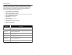
TROUBLESHOOTING GUIDE The following guide is for reference purposes only. Contact a Metrologic representative at 1-800-ID-METRO or 1-800-436-3876 to preserve the limited warranty terms on page 42. Symptoms Possible Cause(s) Solution All Interfaces The unit has no LEDs, beeper or motor spin. No power is being supplied to the scanner. Check the transformer, outlet and power strip. Make sure the cable is plugged into the scanner. The unit has no LEDs and / or beeper.
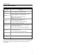
TROUBLESHOOTING GUIDE Symptoms Possible Cause(s) Solution The unit scans a bar code, but locks up after the first scan (the white LED stays on). The scanner is configured to support some form of host handshaking but is not receiving the signal. If the scanner is setup to support ACK/NAK, RTS/CTS, XON/XOFF or D/E, verify that the host cable and host are supporting the handshaking properly. The unit scans but the data transmitted to the host is incorrect.
TROUBLESHOOTING GUIDE Symptoms Possible Cause(s) Solution All Interfaces During power up the unit beeps 3 times. There is a non-volatile RAM failure. Contact a Metrologic service representative. During power up the unit razzes continuously. There is a RAM or ROM failure. Contact a Metrologic service representative. During power up the unit razzes once and the blue LED flashes. There is a VLD failure. Contact a Metrologic service representative.
TROUBLESHOOTING GUIDE Symptoms Possible Cause(s) Solution RS232 Only The host is The scanner and host receiving data may not be configured but the data does for the same interface. not look correct. Characters are being dropped. The intercharacter delay needs to be added to the transmitted output. Check that the scanner and the host are configured for the same interface. Add some intercharacter delay to the transmitted output by using the MetroSelect Configuration Guide (MLPN 00-02407).
DESIGN SPECIFICATIONS MS3780 Operational Light Source: Visible Laser Diode (VLD) @ 650 nm Laser Power: 1.1 mW (Peak) Normal Depth of Field: Reduced Depth of Field: 25 mm - 280 mm (1”- 11”) 25 mm - 150 mm (1”- 6”) 0.33 mm (13 mil) bar code Omni Scan Scan Speed: No. of Scan Lines: 1333 scan lines per second 20 Single-Line Scan Speed: No. of Scan Lines: Motor Speed: Min Bar Width: 67 scan lines per second 1 4000 RPM 0.127 mm (5.
DESIGN SPECIFICATIONS MS3780 Electrical Voltage Supply: Operating Power: Standby Power: 5VDC ± 0.25V 1.375 W 1.0 W Operating Current: 275 mA typical at 5VDC Standby Current: 200 mA typical at 5VDC DC Transformers: Laser Class 1: EMC: Class II; 5.
APPLICATIONS AND PROTOCOLS The model number on each scanner includes the scanner number and factory default communications protocol.
DEFAULT SETTINGS - COMMUNICATION PARAMETERS Many functions of the scanner can be "configured" - that is enabled or disabled. The scanner is shipped from the factory configured to a set of default conditions. The default parameter of the scanner has an asterisk ( * ) in the charts on the following pages. If an asterisk is not in the default column then the default setting is off or disabled. Every interface does not support every parameter.
DEFAULT SETTINGS - COMMUNICATION PARAMETERS PARAMETER Expanded ID “]e0” DEFAULT OCIA USB RS232* LIGHT PEN IBM 46XX KBW * RSS Limited Enable RSS Limited ID “]e0” * RSS Limited App ID “01” * RSS Limited Check Digit * Bars High as Code 39 * Spaces High as Code 39 Bars High as Scanned Spaces High as Scanned DTS/SIEMENS DTS/NIXDORF * NCR F NCR S Poll Light Pen Source Beeper Tone Normal Beep/Transmit Sequence Before Transmit Communication Timeout None Razzberry Tone on Timeout Three Beeps
DEFAULT SETTINGS - COMMUNICATION PARAMETERS PARAMETER Transmit UPC-A Check Digit DEFAULT * Transmit UPC-E Check Digit Expand UPC-E Convert UPC-A to EAN-13 Transmit Lead Zero on UPC-E Convert EAN-8 to EAN-13 Transmit UPC-A Number System * Transmit UPC-A Manufacturer ID# * Transmit UPC-A Item ID# * Transmit Codabar Start/Stop Characters CLSI Editing (Enable) Transmit Mod 43 Check Digit on Code 39 Transmit Code 39 Stop/Start Characters Transmit Mod 10/ITF Transmit MSI-Plessey Check Characters Parity B
DEFAULT SETTINGS - COMMUNICATION PARAMETERS PARAMETER DEFAULT OCIA USB RS232* LIGHT PEN IBM 46XX KBW Nixdorf ID LRC Enabled UPC Prefix UPC Suffix Transmit AIM ID Characters STX Prefix ETX Suffix Carriage Return * Line Feed - disabled by default in KBW * Tab Prefix Tab Suffix “DE” Disable Command “FL” Laser Enable Command DTR Handshaking Support RTS/CTS Handshaking Character RTS/CTS * Message RTS/CTS XON/XOFF Handshaking ACK/NAK Two Digit Supplements as code 39 Five Digit Supplements as code
DEFAULT SETTINGS - COMMUNICATION PARAMETERS PARAMETER DEFAULT Supplements are not Required * Two Digit Redundancy * OCIA USB RS232* LIGHT PEN Five Digit Redundancy 100 msec to Find Supplement Programmable in 100msec steps (MAX 800 msec) * as code 39 Coupon Code 128 Programmable Code Lengths 7 avail. Programmable Prefix Characters 10 avail. Programmable Suffix Characters 10 avail.
UPGRADING THE FLASH ROM FIRMWARE The MetroSet2 program is a functional component of Metrologic’s new line of Flash- based scanners. This program allows the user of a Metrologic scanner to quickly upgrade to a new or custom version of firmware. It requires the use of a personal computer running Windows® 95 or greater and the use of a serial port. The user merely connects the scanner to a serial port on the PC, launches the MetroSet2 program, and blasts off to new software upgrades.
SCANNER AND CABLE TERMINATIONS Scanner Pinout Connections The MS3780 scanner interfaces terminate to a 10-pin modular socket. The serial # label indicates the interface enabled when the scanner is shipped from the factory. Figure 25.
SCANNER AND CABLE TERMINATIONS Figure 26.
SCANNER AND CABLE TERMINATIONS Cable Connector Configurations (Host End) Keyboard Wedge PowerLink Cable 53-53002x-3 Pin 1 2 3 4 5 Pin 1 2 3 4 5 6 Function Keyboard Clock Keyboard Data No Connect Power Ground +5 Volts DC Function PC Data No Connect Power Ground +5 Volts DC PC Clock No Connect 5-Pin DIN, Female 6-Pin DIN, Male Metrologic will supply an adapter cable with a 5-pin DIN male connector on one end and a 6-pin mini DIN female connector on the other.
LASER AND PRODUCT SAFETY Caution Use of controls or adjustments or performance of procedures other than those specified herein may result in hazardous laser light exposure. Under no circumstances should the customer attempt to service the laser scanner. Never attempt to look at the laser beam, even if the scanner appears to be nonfunctional. Never open the scanner in an attempt to look into the device. Doing so could result in hazardous laser light exposure.
LASER AND PRODUCT SAFETY Notices This equipment has been tested and found to comply with limits for a Class A digital device, pursuant to part 15 of the FCC Rules. These limits are designed to provide reasonable protection against harmful interference when the equipment is operated in a commercial environment. This equipment generates, uses and can radiate radio frequency energy and, if not installed and used in accordance with the instruction manual, may cause harmful interference to radio communications.
SCANNER AND CABLE TERMINATIONS Cable Connector Configurations (Host End) RS232 PowerLink Cable 53-53000-3 Pin Function 1 Shield Ground 2 RS232 Transmit Output 3 RS232 Receive Input 4 DTR Input/Light Pen Source 5 Power/Signal Ground 6 7 Light Pen Data CTS Input 8 RTS Output 9 +5VDC 9 5 6 1 9-Pin D-Type Connector USB Power/Communication Cable 53-53213x-N-3, 53-530214x-N-3 or 53-53235x-N-3 Pin 1 Function PC +5V/V_USB 2 D- 3 D+ 4 Ground USB Type A Locking with Power Shield Shield
LIMITED WARRANTY The MS3780 Fusion™ scanners are manufactured by Metrologic at its Blackwood, New Jersey, U.S.A. facility. The MS3780 Fusion scanners have a five (5) year limited warranty from the date of manufacture. Metrologic warrants and represents that all MS3780 Fusion scanners are free of all defects in material, workmanship and design, and have been produced and labeled in compliance with all applicable U.S.
PATENTS Patent Information This METROLOGIC product may be covered by one or more of the following U.S. Patents: U.S. Patent No.
INDEX A E AC ....................................... 2, 7–11 Accessories ...............................2, 3 Adapter..........................................9 Audible Indicator.. 15–17, 23–26, 35 EAS............................................. 12 B Bar Code ............. 15–17, 23–26, 27 Bar Width.....................................27 Beep .............. 15, 16, 17, 23–26, 35 Blue LED ............. 15–17, 23–26, 35 Button ................................4, 13–14 CodeGate .............................
INDEX Light Source ................................27 S M Scan Lines .................................. 27 Scan Pattern ........................... 1, 27 Primary .............................. 13–14 Secondary ......................... 13–14 Single-Line ........................ 13–14 Scan Speed ................................ 27 SELV....................................... 7–11 Single-Line Mode .......................... 4 Specification Electrical.................................. 28 Environmental .......
NOTES
April 2006 Printed in the USA 00 - 02269B