METROLOGIC INSTRUMENTS, INC.
Copyright © 2007 by Metrologic Instruments, Inc. All rights reserved. No part of this work may be reproduced, transmitted, or stored in any form or by any means without prior written consent, except by reviewer, who may quote brief passages in a review, or provided for in the Copyright Act of 1976. Trademarks Metrologic is a registered trademark of Metrologic Instruments, Inc. Products identified in this document are hereby acknowledged as trademarks, registered or otherwise, of Metrologic Instruments, Inc.
TABLE OF CONTENTS Introduction Product Overview ............................................................................................. 1 Scanner and Accessories................................................................................. 2 Scanner Components....................................................................................... 4 The PowerLink Cable ....................................................................................... 5 Labels.....................................
TABLE OF CONTENTS Scanner and Cable Terminations Scanner Pinout Connections .......................................................................... 31 Cable Connector Configurations .................................................................... 33 Limited Warranty ................................................................................................ 35 Regulatory Compliance Safety .............................................................................................................
INTRODUCTION Product Overview The MS1890 is a rugged, high performance hand-held area imaging bar code scanner that utilizes a high-resolution CMOS imaging sensor for superior image ® quality. The MS1890 utilizes Omniplanar, Inc.’s Swiftdecoder software for reliable decoding of both 1D and 2D bar code symbologies. Sharp images can be captured and transmitted in a variety of outputs, including: .jpg, .bmp, and .tiff.
INTRODUCTION Scanner and Accessories BASIC KIT Part # Description MS1890 Area Imaging Bar Code Scanner 00-02544 MetroSelect® Single-Line Configuration Guide* 00-02281 Area Imaging Bar Code Supplemental Configuration Guide* 00-02293 MS1890 Series Area Imaging Bar Code Scanner Installation and User’s Guide* * Available on the Metrologic website - www.metrologic.com OPTIONAL ACCESSORIES Part # Description AC to DC Power Transformer - Regulated 5.2VDC @ 1A output.
INTRODUCTION Scanner and Accessories OPTIONAL ACCESSORIES Part # 53-53713x-N-3 Description USB Full Speed Cable Locking Plus-Power™ Type A, 2.7 m (9 ft.) coiled cord, long strain relief, black USB Full Speed Cable Locking Plus-Power™ Type A, 4.5 m (15 ft.) coiled cord, long strain relief, black 53-53713x-N-3 This cable is for use with full speed USB (-40) interface only. 53-53735x-3 USB Low Speed Communication Cable Type A 2.7 m (9 ft.
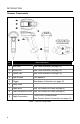
INTRODUCTION Scanner Components No.
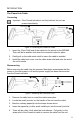
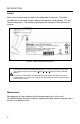
INTRODUCTION The PowerLink Cable Connecting Important: If the PowerLink cable is not fully latched, the unit can power intermittently. Figure 2. Connecting the PowerLink Cable 1. Insert the 10-pin RJ45 end of the cable into the socket on the MS1890. There will be an audible click when the connector locks into place. 2. Gently pull on the cable strain relief to insure the cable is installed. 3. Install the cable boot cover over the cable strain relief and onto the end of the unit’s handle.
INTRODUCTION Labels Each scanner has a label located on the underside of the head. This label provides the unit’s model number, date of manufacture, serial number, CE, and caution information. The following figure gives an example of the label and its location. Figure 4. Label Samples and Location Caution: To maintain compliance with applicable standards, all circuits connected to the scanner must meet the requirements for SELV (Safety Extra Low Voltage) according to EN/IEC 60950-1.
INSTALLING THE SCANNER TO THE HOST SYSTEM RS232 MS1890-14 1. Turn off the host device. 2. Plug the male 10-pin RJ45 end of the PowerLink cable into the 10-pin socket on the MS1890. There will be an audible click when the connector lock engages. 3. Slide the protective cable boot up the cable, over the connector and onto the end of scanner handle. 4. Connect the 9-pin D-type connector of the communication cable to the proper COM port of the host device. 5.
INSTALLING THE SCANNER TO THE HOST SYSTEM Keyboard Wedge MS1890-47 1. Turn off the host device. 2. Plug the 10-pin RJ45 male end of the PowerLink cable into 10-pin socket on the MS1890. There will be an audible click when the connector lock engages. 3. Slide the protective cable boot up the cable, over the connector and onto the end of scanner handle. 4. Disconnect the keyboard from the host device. 5.
INSTALLING THE SCANNER TO THE HOST SYSTEM Stand Alone Keyboard MS1890-47 1. Turn off the host device. 2. Plug the male 10-pin RJ45 end of the PowerLink cable into the 10-pin socket on the MS1890. There will be an audible click when the connector lock engages. 3. Slide the protective cable boot up the cable, over the connector and onto the end of scanner handle. 4. Plug the other end of the communication cable into the host’s keyboard port. 5.
INSTALLING THE SCANNER TO THE HOST SYSTEM IBM MS1890-11 1. Turn off the host device. 2. Plug the male 10-pin RJ45 end of the MVC cable into the 10-pin socket on the MS1890. There will be an audible click when the connector lock engages. 3. Slide the protective cable boot up the cable, over the connector and onto the end of scanner handle. 4. Connect the other end of the MVC cable to the host device. 5. Turn on the host device. 6. The MS1890 will start to initialize.
INSTALLING THE SCANNER TO THE HOST SYSTEM Integrated USB: Full Speed MS1890-40 Low Speed MS1890-38 1. Turn off the host device. 2. Plug the male 10-pin RJ45 end of the USB cable into the 10-pin socket on the MS1890. There will be an audible click when the connector lock engages. 3. Slide the protective cable boot up the cable, over the connector and onto the end of scanner handle. 4. Plug the USB type A end of the USB cable into the host’s USB port. 5. Turn on the host device. 6.
SCANNER OPERATION Multi-Try Trigger Mode* 1. The IR detects an object in the IR activation range and automatically turns on linear illumination. 2. Aim the scanner’s line of light over the bar code. 3. Pull the trigger to initiate scanning. The scanner’s light output will start to flash as it attempts to scan the bar code. If the trigger is released the scanner will stop trying to scan. 4.
SCANNER OPERATION Audible Indicators When the MS1890 is in operation, it provides audible feedback. These sounds indicate the status of the scanner. Eight settings are available for the tone of the beep (normal, 6 alternate tones and no tone). To change the tone, refer to the MetroSelect Single-Line Configuration Guide, MLPN 00-02544 or MetroSet2’s help files. One Beep When the scanner successfully reads a bar code it will beep once and the white LED will turn on indicating data is being transmitted.
SCANNER OPERATION Visual Indicators The MS1890 has three LED indicators (yellow, white and blue) located on the top of the scanner. When the scanner is on, the flashing or stationary activity of the LEDs indicates the status of the current scan and the scanner. No LEDs are Illuminated The LEDs will not be illuminated if the scanner is not receiving power from the host or transformer. The scanner is in stand-by mode.
SCANNER OPERATION Failure Modes Long Razzberry Tone – During Power Up Failed to initialize or configure the scanner. If the scanner does not respond after reprogramming, return the scanner for repair. Short Razzberry Tone – During Scanning An invalid bar code has been scanned when in configuration mode or the trigger has been pulled too fast.
SCANNER OPERATION Depth of Field by Minimum Bar Code Element Width MINIMUM BAR CODE ELEMENT WIDTH 1D PDF A B C D E F G mm .132 .19 .254 .33 .533 .254 .381 mils 5.2 7.5 10.4 13 21 10 15.9 Figure 12. Depth of Field by Minimum Bar Code Element Width Specifications are subject to change without notice.
SCANNER OPERATION IR Activation Range The MS1890 has a built in object detection sensor that instantly turns on the scanner when an object is presented within the scanner’s IR activation Area. Figure 13. IR Activation Area Specifications are subject to change without notice.
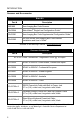
TROUBLESHOOTING GUIDE The following guide is for reference purposes only. Contact a Metrologic representative at 1-800-ID-Metro or 1-800-436-3876 to preserve the limited warranty terms. All Interfaces MS1890 Series Troubleshooting Guide Symptoms Possible Causes Solution No power is being supplied to the scanner. Check transformer, outlet and power strip. Make sure the cable is plugged into the scanner. No power is being supplied to the scanner from the host.
TROUBLESHOOTING GUIDE Symptoms Possible Causes Solution The unit powers The beeper is up, but does not disabled and no tone beep when bar is selected. code is scanned. Enable the beeper and select a tone. The unit powers up, but does not scan and/or beep. The bar code symbology trying to be scanned is not enabled. UPC/EAN, Code 39, interleaved 2 of 5, Code 93, Code 128, Codabar and PDF are enabled by default. Verify that the type of bar code being read has been selected.
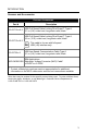
TROUBLESHOOTING GUIDE Symptoms The unit beeps at some bar codes and NOT for others of the same bar code symbology. The unit scans the bar code but there is no data. The unit scans but the data is not correct. 20 Possible Causes Solution The print quality of the bar code is suspect. Check print mode. The type of printer could be the problem. Change print settings (i.e. change to econo mode or high speed). The aspect ratio of the bar code is out of tolerance. Check print mode.
TROUBLESHOOTING GUIDE Symptoms Possible Causes Solution The unit is transmitting each character twice. The configuration is not set correctly. Increase interscan code delay setting. Adjust whether the F0 break is transmitted. It may be necessary to try this in both settings. Alpha characters show as lower case. The computer is in Caps Lock mode. Enable Caps Lock detect setting of the scanner to detect if the PC is operating in Caps Lock. Everything works except for a couple of characters.
DESIGN SPECIFICATIONS MS1890 DESIGN SPECIFICATIONS OPERATIONAL Light Source: LED 645 nm Pulse Duration: 1 ms to 8 ms Maximum Output of an Osram LED: Depth of Scan Field: Field of View: Minimum Bar Width: Infrared Activation: Decode Capability: Maximum 85 mA emits 3,120 mlm 0 mm – 300 mm (0" – 11.81") for 0.330 mm (13 mil) Bar Code at Default Setting 49 mm W x 19 mm H (1.9" W x 0.8" H) at 20 mm (0.8") 264 mm x 106 mm (10.4" W x 4.2" H) at 280 mm (11.0") 0.127 mm (5.0 mil) 1D, 0.254 mm (10.
DESIGN SPECIFICATIONS MS1890 DESIGN SPECIFICATIONS ELECTRICAL Input Voltage: 5.0VDC ± 0.25V Peak = 2 W (Typical) Power: Operating = 1.65 W (Typical) Idle / Standby = 800 mW (Typical) Peak = 400 mA (Typical) Current: Operation = 330 mA (Typical) Idle / Standby = 160 mA (Typical) DC Transformer: Class 2; 5.2VDC @ 1A For Regulatory Compliance information, see pages 36 - 38.
APPLICATIONS AND PROTOCOLS The model number on each scanner includes the scanner number and factory default communications protocol. VERSION IDENTIFIER SCANNER MS1890 - COMMUNICATION PROTOCOL(S) 11 IBM 468X/469X, RS232-TXD, RXD, RTS, CTS 14 RS232 (TX, RX, RTS, CTS, DTR) 38 Low Speed USB 40 Full-speed USB 47 Keyboard Wedge, Stand-Alone Keyboard and RS232 Transmit/Receive The MS1890-47 with a built-in PC Keyboard Wedge Interface is designed for Keyboard emulation use only.
DEFAULT SETTINGS – COMMUNICATION PARAMETERS Many functions of the scanner can be configured or enabled/disabled. The scanner is shipped from the factory configured to a set of default conditions. The default parameter of the scanner has an asterisk (*) in the charts on the following pages. If an asterisk is not in the default column, the default setting is OFF or DISABLED. Every interface does not support every parameter.
DEFAULT SETTINGS – COMMUNICATION PARAMETERS PARAMETER DEFAULT MSI-Plessy 10/10 Check Digit MSI-Plessy Mod 10 Check Digit * Paraf Support ITF RS232 IBM 46XX KBW USB 9 9 9 9 9 9 9 9 9 9 9 9 ITF Symbol Lengths Variable 9 9 9 9 Symbol Length Lock None 9 9 9 9 Beeper tone Normal 9 9 9 9 Beep/transmit sequence Before transmit 9 9 9 9 Communication timeout None 9 9 9 9 Razzberry tone on timeout 9 9 9 9 Three beeps on timeout 9 9 9 9 9 9 9 9 Same symb
DEFAULT SETTINGS – COMMUNICATION PARAMETERS PARAMETER DEFAULT RS232 IBM 46XX KBW USB * 9 9 9 9 Transmit Codabar Start/Stop Characters 9 9 9 9 CLSI Editing (Enable) 9 9 9 9 Transmit Mod 43 Check digit on Code 39 9 9 9 9 Transmit Mod 10/ITF 9 9 9 9 Transmit MSI-Plessy 9 9 9 9 No 9 9 Baud Rate 9600 9 8 Data Bits * 9 Transmit UPC-A Item ID# Parity 9 7 Data Bits Stop Bits 9 1 9 Transmit Sanyo ID Characters 9 9 Nixdorf ID 9 9 LRC Enabled 9 9 UPC Prefix
DEFAULT SETTINGS – COMMUNICATION PARAMETERS PARAMETER DEFAULT RS232 IBM 46XX KBW USB XON/XOFF Handshaking 9 ACK/NAK 9 Two Digit Supplements 9 9 9 9 Five Digit Supplements 9 9 9 9 Bookland 9 9 9 9 977 (2 digit) Supplemental Requirement 9 9 9 9 Supplements are not Required * 9 9 9 9 Two Digit Redundancy * 9 9 9 9 Five digit Redundancy 9 9 9 9 Coupon Code 128 9 9 9 9 † Configurable Code Lengths 7 avail 9 9 9 9 † Code Selects with configurable Code Lengt
CONFIGURATION MODES The MS1890 Series has three modes of configuration. • Bar Codes The MS1890 can be configured by scanning the bar codes included in the Metrologic Single-Line Configuration Guide (MLPN 00-02544) or the Area Imaging Bar Code Supplemental Configuration Guide (MLPN 00-02281). These manuals can be downloaded for FREE from Metrologic’s website (www.metrologic.com).
UPGRADING THE FLASH ROM FIRMWARE The MetroSet2 program is a functional component of Metrologic’s new line of Flash- based scanners. This program allows the user of a Metrologic scanner to quickly upgrade to a new or custom version of firmware. It requires the use of a personal computer running Windows 95 or greater and the use of a serial port. The user merely connects the scanner to a serial port on the PC, launches the MetroSet2 program, and blasts off to new software upgrades.
SCANNER AND CABLE TERMINATIONS Scanner Pinout Connections MS1890-14, RS232 The MS1890 scanner interfaces terminate to a 10-pin, RJ45 Female Socket. The serial # label indicates the interface enabled when the scanner is shipped from the factory.
SCANNER AND CABLE TERMINATIONS Scanner Pinout Connections MS1890-38, Low Speed USB Pin 1 2 3 4 5 6 7 8 9 10 Function Ground RS232 Transmit Output RS232 Receive Input RTS Output CTS Input USB D+ V USB USB D+5VDC Shield Ground MS1890-40, Full Speed USB Pin 1 2 3 4 5 6 7 8 9 10 32 Function Ground RS232 Transmit Output RS232 Receive Input RTS Output CTS Input USB D+ V USB USB D+5VDC Shield Ground Figure 15.
SCANNER AND CABLE TERMINATIONS Cable Connector Configurations (Host End) RS232 PowerLink Cable MLPN 53-53700x-3 Pin Function 1 Shield Ground 2 RS232 Transmit Output 3 RS232 Receive Input 4 DTR Input/Light Pen Source 5 Power/Signal Ground 6 Reserved 7 CTS Input 8 RTS Output 9 +5VDC 9-Pin D-Type Connector Stand-Alone Keyboard PowerLink Cable, MLPN 53-53720-3 Pin 1 Function PC Data 2 NC 3 Power Ground 4 +5VDC PC Power to KB 5 PC Clock 6 NC 6-Pin Male Mini-DIN Connector USB Po
SCANNER AND CABLE TERMINATIONS Cable Connector Configurations (Host End) Keyboard Wedge PowerLink Cable MLPN 53-53702x-3 Pin Function 1 Keyboard Clock 2 Keyboard Data 3 No Connect 4 Power Ground 5 +5 VDC Pin 5-Pin DIN, Female Function 1 PC Data 2 No Connect 3 Power Ground 4 5 6 +5 VDC PC Clock No Connect 6-Pin DIN, Male Metrologic will supply an adapter cable with a 5-pin DIN male connector on one end and a 6-pin mini DIN female connector on the other.
LIMITED WARRANTY The MS1890 series scanners are manufactured by Metrologic at its Blackwood, New Jersey, U.S.A. facility. The MS1890 series scanners have a three (3) year limited warranty from the date of manufacture. Metrologic warrants and represents that all MS1890 series scanners are free of all defects in material, workmanship and design, and have been produced and labeled in compliance with all applicable U.S.
REGULATORY COMPLIANCE Safety ITE Equipment IEC 60950-1, EN 60950-1 LED Class 1 LED Product: IEC 60825-1:1993+A1+A2, EN 60825-1:1994+A1+A2 Caution Use of controls or adjustments or performance of procedures other than those specified herein may result in hazardous radiation exposure. Under no circumstances should the customer attempt to service the LED scanner. Never attempt to look at the LED beam, even if the scanner appears to be nonfunctional.
REGULATORY COMPLIANCE EMC Emissions FCC Part 15, ICES-003, CISPR 22, EN 55022 Immunity CISPR 24, EN 55024 Changes or modifications not expressly approved by the party responsible for compliance could void the user’s authority to operate the equipment. Class A Devices The following is applicable when the scanner cable is greater in length than 3 meters (9.8 feet) when fully extended: Les instructions ci-dessous s’appliquent aux cables de scanner dépassant 3 métres (9.
REGULATORY COMPLIANCE EMC Changes or modifications not expressly approved by the party responsible for compliance could void the user’s authority to operate the equipment. Class B Devices The following is applicable when the scanner cable is less than 3 meters (9.8 feet) in length when fully extended: Les instructions ci-dessous s’appliquent aux cables de scanner ne dépassant pas 3 métres (9.
PATENTS This METROLOGIC product may be covered by, but not limited to, one or more of the following U.S. Patents: U.S. Patent No.
INDEX A AC ................................. 2, 7–11, 23 Accessories ...................................2 Adapter....................................2, 34 Aperture.........................................4 Audible Indicator.............. 14–15, 30 Depth of Field.............................. 16 E EMC................................ 23, 37, 38 EMI ....................................... 37, 38 Emissions.............................. 37, 38 B F Bar Code ................... 18–21, 22, 29 Bar Code Element .
INDEX Light Levels .................................23 Light Source ................................22 M Maintenance..................................6 Meteor .........................................30 MetroSelect ..................... 13, 24, 29 MetroSet2....................................30 Mode of Operation.......................12 N Notices ........................................36 P Specifications Electrical.................................. 23 Environmental .........................
42
June 2007 Printed in the USA 00 - 02293A