00-02098_Cover_Quark_March_2005.qxd 3/11/2005 9:31 AM Page 1 METROLOGIC INSTRUMENTS, INC.
Copyright © 2005 by Metrologic Instruments, Inc. All rights reserved. No part of this work may be reproduced, transmitted, or stored in any form or by any means without prior written consent, except by reviewer, who may quote brief passages in a review, or provided for in the Copyright Act of 1976. Products and brand names mentioned in this document are trademarks of their respective companies.
TABLE OF CONTENTS Introduction ............................................................................................................1 Scanner and Accessories ..................................................................................2 Scanner Components ........................................................................................4 The PowerLink Cable ........................................................................................5 Labels .....................................
TABLE OF CONTENTS Scanner and Cable Terminations Scanner Pinout Connections .......................................................................... 34 Cable Connector Configurations .................................................................... 36 Limited Warranty ................................................................................................ 38 Product Safety Notices ...........................................................................................................
INTRODUCTION The MS1690 Focus is a high performance hand-held area imaging bar code scanner that utilizes high-resolution CMOS imaging sensors for superior image quality. Focus utilized Omniplanar, Inc.’s Swiftdecoder™ software, for reliable decoding of both 1D and 2D bar code symbologies. Sharp images can be captured and transmitted in a variety of outputs including: .jpg, .bmp, and .tiff.
INTRODUCTION Scanner and Accessories BASIC KIT Part # Description MS1690 Focus Area Imaging Bar Code Scanner 00-02544 MetroSelect® Single-Line Configuration Guide* 00-02065 Supplemental Configuration Guide* 00-02098 MS1690 Focus Area Imaging Bar Code Scanner Installation and User’s Guide* * Available on the Metrologic website - www.metrologic.com OPTIONAL ACCESSORIES Part # Description AC to DC Power Transformer - Regulated 5.2VDC @ 650 mA output.
INTRODUCTION Scanner and Accessories OPTIONAL ACCESSORIES Part # 53-53213x-N-3 Description USB Power/Communication Cable, 2.7 m (9 ft.) coiled cord, long strain relief, black USB Power/Communication Cable, 4.5 m (15 ft.) coiled cord, long strain relief, black 53-53214x-N-3 This cable is for use with full speed USB (-40) interface only. 53-53235x-N-3 Low Speed USB Non-Locking Communication Cable 2.7 m (9 ft.
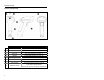
INTRODUCTION Scanner Components Figure 1.
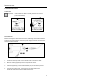
INTRODUCTION THE POWERLINK CABLE CONNECTING Important: If the PowerLink cable is not fully ‘latched’ the unit can power intermittently. Figure 2. Figure 3. DISCONNECTING Before removing the cable from the scanner, Metrologic recommends that the power on the host system is off and the power supply has been disconnected from the PowerLink cable. Figure 4. Releasing the PowerLink Cable 1. Locate the small ‘pin-hole’ on the handle of the unit near the cable. 2.
INTRODUCTION Labels Each scanner has a label located on the underside of the head. This label provides the unit’s model number, date of manufacture, serial number, CE and caution information. The following figure gives an example of the label and its location. Figure 5. Label Samples and Location Maintenance Smudges and dirt can interfere with the proper scanning of a bar code. Therefore, the output window will need occasional cleaning. 6 1.
INSTALLING THE SCANNER TO THE HOST SYSTEM RS232 MS1690-14 1. Turn off the host device. 2. Plug the male 10-pin RJ45 end of the PowerLink cable into the 10-pin socket on the Focus. You will hear a ‘click’ when the connection is made. 3. Connect the 9-pin D-type connector of the communication cable to the proper COM port of the host device. 4. Plug the power supply into the power jack on the PowerLink cable.
INSTALLING THE SCANNER TO THE HOST SYSTEM Keyboard Wedge MS1690-47 1. Turn off the host device. 2. Plug the 10-pin RJ45 male end of the PowerLink cable into 10-pin socket on the Focus. You will hear a ‘click’ when the connection is made. 3. Disconnect the keyboard from the host device. 4. Connect the “Y” ends of the communication cable to the keyboard and keyboard port on the host device. If necessary use the male/female adapter cable supplied with the scanner for proper connections. 5.
INSTALLING THE SCANNER TO THE HOST SYSTEM Stand Alone Keyboard MS1690-47 1. Turn off the host device. 2. Plug the male 10-pin RJ45 end of the PowerLink cable into the 10-pin socket on the Focus. You will hear a ‘click’ when the connection is made. 3. Plug the other end of the communication cable into the host’s keyboard port. 4. Plug the external power supply into the power jack on the PowerLink cable. Check the AC input requirements of the power supply to make sure the voltage matches the AC outlet.
INSTALLING THE SCANNER TO THE HOST SYSTEM IBM MS1690-11 1. Turn off the host device. 2. Plug the male 10-pin RJ45 end of the MVC cable into the 10-pin socket on the Focus. You will hear a ‘click’ when the connection is made. 3. Connect the other end of the MVC cable to the host device. 4. Turn on the host device. 5. Focus will start to initialize. All LEDs (yellow, white, and blue) will light for approximately 2 seconds then start to alternately flash.
INSTALLING THE SCANNER TO THE HOST SYSTEM Integrated USB: Full Speed MS1690-40 Low Speed MS1690-38 1. Turn off the host device. 2. Plug the male 10-pin RJ45 end of the USB cable into the 10-pin socket on the Focus. You will hear a ‘click’ when the connection is made. 3. Plug the USB type A end of the USB cable into the host’s USB port. 4. Turn on the host device. 5. Focus will start to initialize.
STAND KITS STAND COMPONENTS, MLPN 46-00147 Figure 11. Stand Components 12 Item Description Qty. a. Stand Base Qty. 1 b. Flexible Shaft Qty. 1 c. Flexible Shaft Cover Qty. 1 d. Scanner Cradle Qty. 1 e. ¼" – 20 x 3/8" Flat Head Phillips, 82° Undercut Qty. 2 f. #8 Round Head Wood Screw Qty.
STAND KITS HARD MOUNTING THE STAND (OPTIONAL) Metrologic provides two #8 wood screws for securing the stand base to the counter top. The following figure provides the pilot hole dimensions for securing the stand base. Figure 12.
STAND KITS ASSEMBLING THE STAND Figure 13.
SCANNER OPERATION TWO DEFAULT MODES OF OPERATION* CodeGate, Out of Stand 1. The IR detects an object in the IR activation range and automatically turns on linear illumination. 2. Aim the scanner’s line of light over the bar code. 3. Pull the trigger to initiate scanning. The scanner’s light output will start to flash as it attempts to scan the bar code. If the trigger is released the scanner will stop trying to scan. 4.
SCANNER OPERATION Audible Indicators When the Focus is in operation, it provides audible feedback. These sounds indicate the status of the scanner. Eight settings are available for the tone of the beep (normal, 6 alternate tones and no tone). To change the tone, refer to the MetroSelect Single-Line Configuration Guide, MLPN 00-02544 or MetroSet2’s help files. One Beep When the scanner successfully reads a bar code it will beep once and the white LED will turn on indicating data is being transmitted.
SCANNER OPERATION Visual Indicators The MS1690 has three LED indicators (yellow, white and blue) located on the top of the scanner. When the scanner is on, the flashing or stationary activity of the LEDs indicates the status of the current scan and the scanner. No LEDs are Illuminated The LEDs will not be illuminated if the scanner is not receiving power from the host or transformer. The scanner is in stand-by mode.
SCANNER OPERATION Failure Modes Long Razzberry Tone – During Power Up Failed to initialize or configure the scanner. If the scanner does not respond after reprogramming, return the scanner for repair. Short Razzberry Tone – During Scanning An Invalid bar code has been scanned when in configuration mode or the trigger has been pulled too fast.
SCANNER OPERATION Depth of Field by Minimum Bar Code Element Width Figure 16. Depth of Field by Minimum Bar Code Element Width MINIMUM BAR CODE ELEMENT WIDTH 1D PDF A B C D E F G mm .132 .19 .254 .33 .533 .254 .381 mils 5.2 7.5 10.4 13 21 10 15.9 Specifications are subject to change without notice.
SCANNER OPERATION IR Activation Range The MS1690 has a built in object detection sensor that instantly turns on the scanner when an object is presented within the scanner’s IR activation Area. Figure 17. IR Activation Area Specifications are subject to change without notice.
TROUBLESHOOTING GUIDE The following guide is for reference purposes only. Contact a Metrologic representative at 1-800-ID-Metro or 1-800-436-3876 to preserve the limited warranty terms. All Interfaces MS1690 Series Troubleshooting Guide Symptoms Possible Causes Solution No power is being supplied to the scanner. Check transformer, outlet and power strip. Make sure the cable is plugged into the scanner. No power is being supplied to the scanner from the host.
TROUBLESHOOTING GUIDE Symptoms Possible Causes Solution The unit powers The beeper is up, but does not disabled and no tone beep when bar is selected. code is scanned. Enable the beeper and select a tone. The unit powers up, but does not scan and/or beep. The bar code symbology trying to be scanned is not enabled. UPC/EAN, Code 39, interleaved 2 of 5, Code 93, Code 128, Codabar and PDF are enabled by default. Verify that the type of bar code being read has been selected.
TROUBLESHOOTING GUIDE Symptoms The unit beeps at some bar codes and NOT for others of the same bar code symbology. The unit scans the bar code but there is no data. The unit scans but the data is not correct. Possible Causes Solution The print quality of the bar code is suspect. Check print mode. The type of printer could be the problem. Change print settings (i.e. change to econo mode or high speed). The aspect ratio of the bar code is out of tolerance. Check print mode.
TROUBLESHOOTING GUIDE Symptoms Possible Causes Solution The unit is transmitting each character twice. The configuration is not set correctly. Increase interscan code delay setting. Adjust whether the F0 break is transmitted. It may be necessary to try this in both settings. Alpha characters show as lower case. The computer is in Caps Lock mode. Enable Caps Lock detect setting of the scanner to detect if the PC is operating in Caps Lock. Everything works except for a couple of characters.
DESIGN SPECIFICATIONS MS1690 DESIGN SPECIFICATIONS OPERATIONAL Light Source: LED 645 nm Pulse Duration: 1 ms to 8 ms Maximum Output of an Osram LED: Depth of Scan Field: Field of View: Minimum Bar Width: Infrared Activation: Decode Capability: Maximum 85 mA emits 3,120 mlm 0 mm – 230 mm (0" – 9") for 0.330 mm (13 mil) Bar Code at Default Setting 49 mm W x 19 mm H (1.9” W x 0.8” H) at 20 mm (0.8”) 264 mm x 106 mm (10.4” W x 4.2” H) at 280 mm (11.0”) 0.127 mm (5.
DESIGN SPECIFICATIONS MS1690 DESIGN SPECIFICATIONS ELECTRICAL Input Voltage: 5.0VDC ± 0.25V Peak = 2 W (Typical) Power: Operating = 1.65 W (Typical) Idle / Standby = 800 mW (Typical) Peak = 400 mA (Typical) Current: Operation = 330 mA (Typical) Idle / Standby = 160 mA (Typical) DC Transformer: EMC: Class 1 LED Product: Class 2; 5.
APPLICATIONS AND PROTOCOLS The model number on each scanner includes the scanner number and factory default communications protocol. VERSION IDENTIFIER SCANNER MS1690 - COMMUNICATION PROTOCOL(S) 11 IBM 468X/469X, RS232-TXD, RXD, RTS, CTS 14 RS232 (TX, RX, RTS, CTS, DTR) 38 Low Speed USB 40 Full-speed USB 47 Keyboard Wedge, Stand-Alone Keyboard and RS232 Transmit/Receive The MS1690-47 with a built-in PC Keyboard Wedge Interface is designed for Keyboard emulation use only.
DEFAULT SETTINGS – COMMUNICATION PARAMETERS Many functions of the scanner can be “configured” – that is, enabled or disabled. The scanner is shipped from the factory programmed to a set of default conditions. The default parameter of the scanner has an asterisk (*) in the charts on the following pages. If an asterisk is not in the default column then the default setting is OFF or DISABLED. Every interface does not support every parameter.
DEFAULT SETTINGS – COMMUNICATION PARAMETERS PARAMETER RS232 IBM 46XX KBW USB Maxicode 9 9 9 9 Aztec 9 9 9 9 Postals 9 9 9 9 Mod 43 Check on Code 39 9 9 9 9 MSI-Plessy 10/10 Check Digit 9 9 9 9 9 9 9 9 9 9 9 9 MSI-Plessy Mod 10 Check Digit DEFAULT * Paraf Support ITF ITF Symbol Lengths Variable 9 9 9 9 Symbol Length Lock None 9 9 9 9 Beeper tone Normal 9 9 9 9 Beep/transmit sequence Before transmit 9 9 9 9 Communication timeout None 9 9 9
DEFAULT SETTINGS – COMMUNICATION PARAMETERS PARAMETER DEFAULT Transmit lead zero on UPC-E RS232 IBM 46XX KBW USB 9 9 9 9 Transmit UPC-A number system * 9 9 9 9 Transmit UPC-A Manufacturer ID# * 9 9 9 9 Transmit UPC-A Item ID# * 9 9 9 9 Transmit Codabar Start/Stop Characters 9 9 9 9 CLSI Editing (Enable) 9 9 9 9 Transmit Mod 43 Check digit on Code 39 9 9 9 9 Transmit Mod 10/ITF 9 9 9 9 Transmit MSI-Plessy 9 9 9 9 No 9 9 Baud Rate 9600 9 8 Data Bits
DEFAULT SETTINGS – COMMUNICATION PARAMETERS PARAMETER DEFAULT RS232 IBM 46XX KBW USB XON/XOFF Handshaking 9 ACK/NAK 9 Two Digit Supplements 9 9 9 9 Five Digit Supplements 9 9 9 9 Bookland 9 9 9 9 977 (2 digit) Supplemental Requirement 9 9 9 9 Supplements are not Required * 9 9 9 9 Two Digit Redundancy * 9 9 9 9 Five digit Redundancy 9 9 9 9 Coupon Code 128 9 9 9 9 † Configurable Code Lengths 7 avail 9 9 9 9 † Code Selects with configurable Code Lengt
CONFIGURATION MODES The MS1690 Focus Series has three modes of configuration. • Bar Codes The MS1690 can be configured by scanning the bar codes included in the Metrologic Single-Line Configuration Guide (MLPN 00-02544). This manual can be downloaded for FREE from Metrologic’s website (www.metrologic.com). • MetroSet2 This user-friendly Windows-based configuration program allows you to simply ‘point-and-click’ at the desired scanner options.
UPGRADING THE FLASH ROM FIRMWARE The MetroSet2 program is a functional component of Metrologic’s new line of Flash- based scanners. This program allows the user of a Metrologic scanner to quickly upgrade to a new or custom version of firmware. It requires the use of a personal computer running Windows 95 or greater and the use of a serial port. The user merely connects the scanner to a serial port on the PC, launches the MetroSet2 program, and blasts off to new software upgrades.
SCANNER AND CABLE TERMINATIONS Scanner Pinout Connections MS1690-14, RS232 The MS1690 scanner interfaces terminate to a 10-pin, RJ45 Female Socket. The serial # label indicates the interface enabled when the scanner is shipped from the factory.
SCANNER AND CABLE TERMINATIONS MS1690-38, Low Speed USB Pin 1 2 3 4 5 6 7 8 9 10 Function GND/USBTransmit Receive RTS Output CTS Input D+ USB + V D+5VDC Shield Ground MS1690-40, Full Speed USB Pin 1 2 3 4 5 6 7 8 9 10 Function GND/USBTransmit Receive RTS Output CTS Input D+ USB + V D+5VDC Shield Ground Figure 19.
SCANNER AND CABLE TERMINATIONS Cable Connector Configurations (Host End) “Standard” PowerLink Cable 53-53000-3 Coiled Pin Function 1 Shield Ground 2 RS232 Transmit Output 3 RS232 Receive Input 4 DTR Input/Light Pen Source 5 Power/Signal Ground 6 Reserved 7 CTS Input 8 RTS Output 9 +5VDC 9 5 6 1 9-Pin D-Type Connector Stand Alone Keyboard PowerLink Cable 53-53020-3 Pin 1 2 3 4 5 6 Function PC Data NC Power Ground +5VDC PC Power to KB PC Clock NC 1 2 4 3 6 5 6-Pin Male Mini-DIN
SCANNER AND CABLE TERMINATIONS Cable Connector Configuration (Host End) Keyboard Wedge PowerLink Cable 53-53002-3 Coiled Pin 1 2 3 4 5 Pin 1 2 3 4 5 6 Function Keyboard Clock Keyboard Data No Connect Power Ground +5 VDC Function PC Data No Connect Power Ground +5 VDC PC Clock No Connect 4 2 5 1 3 5-Pin DIN, Female 1 2 4 3 6 5 6-Pin DIN, Male Metrologic will supply an adapter cable with a 5-pin DIN male connector on one end and a 6-pin mini DIN female connector on the other.
LIMITED WARRANTY The MS1690 Focus™ scanners are manufactured by Metrologic at its Blackwood, New Jersey, U.S.A. facility. The MS1690 Focus scanners have a five (5) year limited warranty from the date of manufacture. Metrologic warrants and represents that all MS1690 Focus scanners are free of all defects in material, workmanship and design, and have been produced and labeled in compliance with all applicable U.S.
PRODUCT SAFETY Notices This equipment has been tested and found to comply with limits for a Class A digital device, pursuant to part 15 of the FCC Rules. These limits are designed to provide reasonable protection against harmful interference when the equipment is operated in a commercial environment. This equipment generates uses, and can radiate radio frequency energy and, if not installed and used in accordance with the instruction manual, may cause harmful interference to radio communications.
PRODUCT SAFETY Caution Use of controls or adjustments or performance of procedures other than those specified herein may result in hazardous radiation exposure. Under no circumstances should the customer attempt to service the LED scanner. Never attempt to look at the LED beam, even if the scanner appears to be nonfunctional. Never open the scanner in an attempt to look into the device. Doing so could result in hazardous radiation exposure.
PATENTS Worldwide Patents Pending 41
INDEX A AC ..................................2, 7–11, 26 Accessories....................................2 Adapter ....................................2, 37 Aperture .........................................4 Audible Indicator ..............17–18, 33 B Bar Code................... 21–24, 25, 32 Bar Code Element........................19 Beep.............. 17–18, 21–24, 25, 33 Blue LED........... 4, 7–11, 17–18, 33 Depth of Field ..............................19 E EMC..........................................
INDEX M Maintenance ..................................6 Meteor..........................................33 MetroSelect......................16, 27, 32 MetroSet2 ....................................33 Mode of Operation .......................15 N Notices .........................................39 P Patent...........................................41 PDF..............................................19 Pinouts ...................... 34–35, 36–37 Power.......................... 7–11, 26, 33 Power Supply.......
NOTES 44
CONTACT INFORMATION AND OFFICE LOCATIONS CORPORATE HEADQUARTERS NORTH AMERICA USA, New Jersey Metrologic Instruments, Inc. Tel: 1-800-ID-METRO Fax: 856-228-6673 Email: info@metrologic.com SOUTH AMERICA AND CENTRAL AMERICA Brazil São Paulo Metrologic do Brasil Ltda. Tel: 55-11-5182-8226 Fax: 55-11-5182-8315 Email: info@br.metrologic.com EUROPEAN, MIDDLE EAST & AFRICAN HEADQUARTERS Germany, Munich Metrologic Instruments GmbH Tel: 49-89-89019-0 Fax: 49-89-89019-200 Email: info@europe.metrologic.
April 2005 Printed in the USA 00 - 02098B