IS4920, IS4921 Area Imaging Decode Engine Integration Guide
Disclaimer Honeywell International Inc. (“HII”) reserves the right to make changes in specifications and other information contained in this document without prior notice, and the reader should in all cases consult HII to determine whether any such changes have been made. The information in this publication does not represent a commitment on the part of HII.
Table of Contents Introduction Product Overview ..............................................................................................................................................1 Models and Accessories ...................................................................................................................................2 Components of the IS4920 / IS4921 Decode Engine IS4920-0 / IS4921-0 (Bracket Not Included) .........................................................................
Theory of Operation Overview .........................................................................................................................................................16 Host Interface Signals .....................................................................................................................................17 Usage of Host Interface Signals ......................................................................................................................
Regulatory Compliance Safety ..............................................................................................................................................................46 Europe..........................................................................................................................................................46 United States................................................................................................................................................
Introduction Product Overview The IS4920 is a miniature area-imaging engine and decode board with image capturing and bar code decoding capabilities. The engine module consists of a non-decode imaging engine (IS4910), a decode board and two flex cables. The IS4920 features a mega-pixel CMOS sensor, integrated illumination, and patented FirstFlash® technology; together they ensure capturing a high-resolution image with optimal brightness each time.
Models and Accessories Figure 1.
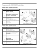
Components of the IS4920 / IS4921 Decode Engine IS4920-0 / IS4921-0 (Bracket Not Included) Item No. Description 1 IS4920-0 / IS4921-0 Assembled Decode Engine 2 IS4910 / IS4911 Non-Decode Engine* See pages 2, 4 and 6 for model specifications. 3 Decode Board* USB (See page 10) TTL Level RS232 (See page 10) 4 Flex Cable P/N 77-77104 Item Location Figure 2. IS4920-0 / IS4921-0 * IS4920-1 / IS4921-1 (Bracket Included) Item No.
Components of the IS4910 / IS4911 Non-Decode Engine Item No. Description 1 Targeting 2 Area Illumination 3 Camera Imager 4 FirstFlash Aperture Item Location Figure 4. IS4910-00 / IS4911-00 5 Mounting Points (see pages 7 - 8) 6 Mounting Points Provided for Self-Tapping Screw (see pages 6 - 8) 7 Keying Location (see pages 6 - 8) 8 Printed Circuit Boards 9 22-Pin, 0.50 mm (.020") Pitch SlimStack™ Plug, Molex (P/N 55560-0227) Figure 5.
Components of the Decode Printed Circuit Board TTL Level RS232 See page 10 for printed circuit board dimensions and connector information. See page 39 and page 41 for connector pinout information. USB See page 10 for printed circuit board dimensions and connector information. See page 39 and page 40 for connector pinout information. Labels The serial number/model number label is located on the side of the engine. Figure 6. Serial Number Label Sample Figure 7.
Mounting Specifications IS4910-00 and IS4911-00 Non-Decode Engine Dimensions The -00 models include two Ø .075" [1.9 mm] blind holes for mounting the engine with self-tapping screws. The mounting holes are located on the bottom of the unit with an additional keying location point for engine alignment. Warning: The limited warranty (on page 49) is void if the following guidelines are not adhered to when mounting the engine. When securing the engine with screws: • Use M2.2 x 4.
IS4910-01 / IS4911-01 Non-Decode Engine Dimensions The -01 models include two Ø .075" [1.9 mm] blind holes for mounting the engine with self-tapping screws. Two additional Ø .098" ± .002 [2.5 mm ±.05 mm] clearance holes are provided as a secondary mounting option. The clearance holes are located on tabs that extend from the sides of the engine's chassis. A keying location point is provided on the bottom of the engine to assist with alignment.
IS4910-02 / IS4911-02 Non-Decode Engine Dimensions The -02 models include two Ø .075" [1.9 mm] blind holes for mounting the engine with self-tapping screws. Two additional M2 x .4 threaded inserts are provided as a secondary mounting option. The threaded inserts are located on tabs that extend from the sides of the engine's chassis. A keying location point is provided on the bottom of the engine to assist with alignment.
Figure 10.
Decode Printed Circuit Board Dimensions Both the TTL Level RS232 decode board and the USB decode board have two Ø 0.098" [2.489 mm] clearance holes for M2.2 mounting hardware. Always use safe ESD practices when handling and mounting the decode board. TTL Level RS232 Figure 11. TTL Level RS232 Decode Board USB Figure 12.
IS4920-2 / IS4921-2 Bracketed Decode Engine Dimensions The bracketed decode engine includes two Ø 0.097" [2.464 mm] blind holes for mounting the engine with self-tapping screws. Two additional M2 x .4 threaded inserts are provided as a secondary mounting option. The threaded inserts are located on tabs that extend from the sides of the engine's chassis. A keying location point is provided on the bottom of the engine to assist with alignment.
Enclosure Specifications The imaging engine was specifically designed for integration into custom housings for OEM applications. The imaging engine’s performance will be adversely affected or permanently damaged when mounted in an unsuitable enclosure. Warning: The limited warranty (on page 49) is void if the following considerations are not adhered to when integrating the area-imaging engine into a system.
Output Window Properties An improperly placed window has a serious potential to reduce the imaging engine’s performance. Careful consideration must be made when designing the output window’s distance and angle relative to the imaging engine’s camera aperture. Follow these guidelines when designing the output window. • The output window material should have a spectral transmission of at least 85% from 580 nm to 680 nm and should block shorter wavelengths.
Optical Clearance Specifications The window size and enclosure design must provide unobstructed clearance for the illumination and targeting areas shown below in figures 14 and 15 to avoid optical interference that decreases the engine's performance. IS4910 Figure 14. IS4910 Optical Clearance Specifications IS4911 Figure 15.
System Considerations In order to ensure proper operation of the decode engine’s electrical system; care must be taken to ensure the following requirements are met. Power Supply* The decode engine is powered from the host device via the VIN and GND pins of the ZIF connector on the decode board. This voltage must be maintained within the specified voltage range at the decode board (see electrical specifications on page 34). Voltage drops in the host flex cable must be taken into account.
Theory of Operation Overview The IS4920 decode imaging engine series is ideal for integration into data terminals and other small devices. The high-quality images produced by the imaging engine can be used for decoding bar codes, image upload, signature capture, document lifting and reading OCR fonts.
Host Interface Signals The host interface signals are described in the table below. Pin# TTL RS232 USB Description 1 232INV NC Input: TTL RS232 polarity control with 32k ohm pull-up. Connect to ground for UART to UART signal polarity. Pull up to Vin for standard TTL RS232 polarity. 2 Vin Vin Power: Supply voltage input (3V to 5.5V) 3 GND GND Ground: Power and signal ground. D- Input: TTL Level RS232 Receive data input, weak pull up to Vin.
Since many host systems and applications have unique formats and protocol requirements, the decode engine supports a wide range of configurable features. These features may be selected by scanning a corresponding configuration bar code from the MetroSelect Single-Line Configuration Guide or Area Imaging Bar code Supplemental Configuration Guide. Both guides are available for download at www.honeywell.com/aidc under the IS4920 product page.
The nTrig signal not only wakes the engine up, but also immediately activates and turns the engine into the Operating Mode. Either nWake or nTrig signals can be used to restart the TTL RS232 scanning engine when the engine is in Power-down Mode, which is indicated by the asserted (high) PWRDWN signal. The PWDWN pin is used to indicate when the decode engine is in various operating modes such as Power Down, Suspend, and Boot.
Power Mode Descriptions Boot Mode The engine is booting up. PWRDWN Pin State: Asserted (HIGH). Transition to Boot Mode: • The TTL RS232 engine is turned to Boot Mode from Power Down Mode when the power is applied AND upon reception of the nTrig or nWake signals. • The USB engine enters Boot Mode upon completion of USB enumeration. • The engine can turn itself to Boot Mode from Operating Mode or Idle Mode upon some internal event, such as at the end of the software upgrade procedure.
Sleep Mode The engine is sleeping, but is fully powered. The CPU is in sleep mode. The image sensor is in standby mode, the wakeup from the Sleep Mode requires the image sensor reprogramming (which is done automatically in the engine software). PWRDWN Pin State: De-asserted (LOW). Transition to Sleep Mode: • The engine is turned to Sleep Mode from Idle Mode upon the expiration of the “sleep” timeout, which is set to one second by default.
Serial Configuration † The IS4920 series can be configured by scanning configuration bar codes or by serial commands sent from the host device. With serial configuration, each command sent to the engine is the ASCII representation of each numeral in the configuration bar code (see Figure 19). The entire numeric string is framed with an ASCII [stx] and an ASCII [etx]. Do Not Include in the Command ³ 1 0 0 1 0 4 Include in the Command Figure 19.
Example 2: The following sample illustrates the serial command sequence for configuring the engine for the factory default settings, disabling Code 128 scanning, and adding a “G” as a configurable prefix. Commands for features that require sequences of multiple bar codes for activation (i.e. prefixes, suffixes, and timeout features) should be sent in the same order that they are normally scanned.
Operational Timing The following section describes the timing associated with the various operating modes of the decode engine assembly including Power Up, Power Down, and Operating (from Idle or Sleep). The waveforms shown in this section assume VIN = 3.3V, nGoodRead pulled up with 10K resistor to VIN, and nBeeper pulled up with 10K resistor to VIN, unless otherwise noted. Power Up / Boot Up The power up sequence of the decode engine depends on the interface type.
The TTL version of the decode engine does not have an on board microcontroller to control the power to the decode platform and imaging engine. As such, the TTL version can only enter Boot Mode in response to signals from the host (nTrig or nWake). When VIN is initially applied with the nWake and nTrig signals held high, the unit will be in the Power Down Mode. In this state, the PWRDWN signal will be high and all other output signals will be in their default state.
Notes: In Figure 21 , the nGoodRead, nBeeper, and PWRDWN signals are high while in the Power Down Mode. The RTS Signal will be high in Power Down Mode regardless of the RTS polarity software configuration. Also, the RTS signal may have the incorrect polarity when the device first enters Boot Mode (Figure 23) or right before the unit enters Power Down Mode (Figure 24). The USB version can be placed into Suspend Mode via the USB suspend signal for low current consumption.
Decode Timing Engine image acquisition or decoding can occur from either the Idle Mode or the Sleep Mode. The process is initiated by asserting the nTrig signal (or serial command when in the Idle Mode). Once the trigger signal is received, the image sensor is reset and image acquisition begins. During image acquisition, the illumination LEDs are enabled for a time determined by the FirstFlash circuitry on the non-decode engine. The image is then transferred to the processor and decoded.
Summary of Operation Timings Operation Timing Specifications Parameter Description Typical 6 seconds Relevant Note(s) Tprw_up Power Applied to Processor Ready Delay (USB) Notes 4 and 5 Tprw_up_ttl Trigger or Wake Low to Processor Ready Delay (TTL) 5 seconds Note 4 Tdec_idle Trigger Low to Decode complete Delay 90 msec Notes 1 and 2 Tdec_sleep Trigger Low to Decode complete Delay 120 msec Notes 1 and 3 Trig_min Minimum Duration of Trigger Signal 20 msec Trig_wake_min_pu Minimum Activati
Depth of Field vs. Bar Code Element IS4920 Bar Code Element Width 1D PDF Data Matrix * Depth of Field* (In the Field of View) Start (From Engine Face) Total End (From Engine Face) .127 mm 5 mil 50 mm (2.0") 145 mm (5.7") 95 mm (3.7") .254 mm 10 mil 30 mm (1.2") 210 mm (8.3") 180 mm (7.1") .330 mm 13 mil 25 mm (1.0") 310 mm (12.2") 285 mm (11.2") .127 mm 5 mil 45 mm (1.8") 160 mm (6.3") 115 mm (4.5") .254 mm 10 mil 25 mm (1.0") 270 mm (10.6") 245 mm (9.6") .
IS4921 Depth of Field* in the Field of View Bar Code Element Width Start End (From Engine Face) (From Engine Face) Total .076 mm 3 mil 68 mm (2.7") 105 mm (4.1") 37 mm (1.4") .127 mm 5 mil 50 mm (2.0") 120 mm (4.7") 70 mm (2.75") .330 mm 13 mil 50 mm (2.0") 170 mm (6.7") 120 mm (4.7") PDF .127 mm 5 mil 45 mm (1.8") 130 mm (5.0") 85 mm (3.2") Data Matrix and QR .127 mm 5 mil 75 mm (3.0") 115 mm (4.5") 40 mm (1.5") 1D * Depth of field information is for reference only.
Exposure Time for Image Acquisition By default, the maximum exposure time for image acquisition is 8 ms. Reducing the exposure time for image acquisition may improve the reading performance of high-density bar codes for certain applications. Use the following bar codes to set the desired maximum exposure time.
Design Specifications Operational Light Source: Four, 650 nm Red Light Emitting Diode LED IS4920 25 mm – 310 mm (1.0" to 12.2") for 0.330 mm (13 mil) 1D Bar Codes See page 29 for additional information on engine depth of field. IS4921 50 mm – 170 mm (2.0" to 6.7") for 0.330 mm (13 mil) 1D Bar Codes See page 30 for additional information on engine depth of field. Depth of Field: 50° Horizontal IS4920 37.5° Vertical Field of View: 38° Horizontal IS4921 28.5° Vertical 118.4 mm x 86.2 mm (4.7" x 3.
Mechanical Dimensions: See pages 6 - 8 for detailed specifications. Weight: < 14 g (.494 oz.) 12-Pin, Molex FFC/FPC Connector (Molex P/N 52559-1252) Termination: See page 38 for engine pinouts. See page 42 for flex cable specifications. Mounting: See pages 6 - 11 for detailed specifications. Keying Location: See pages 6 - 11 for detailed specifications. FFC/FPC is a trademark of Molex, Inc., all rights reserved.
Electrical Engine Input Voltage: 3.3VDC ~ 5.5VDC Typical Operating Current: 235 mA (continuous scan mode, VIN=3.3V) USB TTL Peak Operating Current: 400 mA (typical VIN=3.3V @ 25°C) 400 mA (typical VIN=3.3V @ 25°C) Idle Current: 160 mA (typical VIN=3.3V @ 25°C) 125 mA (typical VIN=3.3V @ 25°C) Sleep Current: 65 mA (typical VIN=3.3V @ 25°C) Suspend Current (USB): 600 µA* (typical VIN=3.3V @ 25°C) Power Down Current (TTL): N/A 25 mA (typical VIN=3.3V @ 25°C) N/A 500 µA* (typical VIN=3.
DC Operating Voltages Signal Signal Description MIN MAX VIN Operating Voltage 3V 5.5V VIH(1) Input High (RX, CTS) 2.
Current Waveforms Figure 29 - Figure 31 show typical current signature for the decode engine (USB version) in various operating modes. Note: The next three waveforms are shown with VIN = 3.3V and the output signals nBeeper and nGoodRead are pulled high externally through 10K resistors. Thus, these waveforms only account for the current drawn by the IS4920 circuitry and does not show additional current required for driving the LED or Beeper. The IS4920 series engines do not have current limiting fuses.
Figure 31.
Imaging Engine and Decode PCB Terminations Imaging Engine Interface Connector Figure 32.
Decode Board (USB & TTL) Interface Connector Figure 33.
Decode Board (USB) Output to Host Connector Figure 34. Decode Board (USB) Output Connector Pin Signal Name Function 1 N/C No Connection 2 Vin Power: Supply voltage input (3V to 5.5V) 3 GND Ground: Power and signal ground. 4 D- Input: USB D- Signal 5 Pin Function Reserved. 6 D+ Input: USB D+ Signal 7 Pin Function Reserved. 8 PWRDWN Output: active high = IS4920 is in power down mode. 9 nBEEPER Output: active low signal capable of sinking current.
Decode Board (TTL) Output to Host Connector Figure 35. Decode Board (TTL) Output Connector Pin Signal Name Function 1 232INV Input: TTL RS232 polarity control with 32k ohm pull-up. 2 Vin Power: Supply voltage input (3V to 5.5V) 3 GND Ground: Power and signal ground. 4 (n)RxD Input: TTL Level RS232 Receive data input. 5 (n)TxD Output: TTL Level RS232 transmit data. 6 (n)CTS Input: TTL level Clear to Send. 7 (n)RTS Output: TTL level RS232 Request to Send.
Flex Cable Specifications Flex Cable Pinout – Imaging Engine Connection Figure 36.
Flex Cable Pinout – Decode Board Connection Figure 37.
Dimensions Figure 38. Flex Cable Dimensions, P/N 77-77104 See installation warning on page 45.
Installation Notes Note 1. Warning! The flex cable must be installed in the orientation shown in Figure 39 and Figure 40. If the cable is incorrectly installed, the engine can be damaged, and the warranty voided, see page 49. Figure 39. Flex Cable Orientation – Imaging Engine Figure 40. Flex Cable Orientation – Decode Board Note 2. Proper installation of the flex cable is essential for engine performance.
Regulatory Compliance Safety The IS4920 Series area imaging engines are designed to meet the requirements of IEC Class 1 in accordance with IEC 60825-1:1993+A1+A2. IEC Class 1 is defined as follows: The specifications required for agency approval are not obtainable until the IS4920 or IS4911 area imaging engine is used in its final configuration. Honeywell International Inc.
United States EMC All combinations of imaging engines and associated electronics will require testing to insure compliance with the following Federal Communications Commission regulation: 47 CFR Part 15 Note: When using the imaging engine with RF equipment, modems, etc. may require examination(s) to the standard(s) for the specific equipment combination. It is the manufacturers’ responsibility to comply with the applicable federal regulation(s).
EMI The IS4920 consists of a 400MHz processor running a 100MHz SDRAM bus and a camera interface capable of image transfer up to 48MHz. The IS4920 series engine was designed to meet EN55022 Radiated Class B emission limits. Using the system shown below, the decode engine was able to meet these requirements with an input voltage VIN = 3.3V and the camera interface operating at its maximum frequency of 48MHz. Figure 41.
Limited Warranty Honeywell International Inc. ("HII") warrants its products and optional accessories to be free from defects in materials and workmanship and to conform to HII’s published specifications applicable to the products purchased at the time of shipment.
Patents This Honeywell product may be covered by, but not limited to, one or more of the following U.S. Patents: U.S. Patent No.
Index A H Aiming............................................................ 16, 34 Ambient Light....................................................... 16 Ambient Temperature .......................................... 15 Area Illumination .................................................... 4 ASCII ............................................................. 22, 23 Assembly ............................................................... 3 Humidity....................................................
Plug.......................................................... 32, 37–41 Power................................................................... 15 Power Supply....................................................... 15 R Receptacle............................................... 16, 44, 45 Regulatory Compliance ................................. 46, 47 Resolution............................................................ 32 RMA.....................................................................
Contact Information The Americas (TA) Germany USA Tel: 49-89-89019-0 Fax: 49-89-89019-200 Email: info@de.metrologic.com Tel: 800.436.3876 (Customer Service) 866.460.8033 (Customer Support) 888.633.3762 (Technical Support) Fax: 856.228.6673 (Sales) 856.228.1879 (Marketing) 856.228.0653 (Legal/Finance) Italy Tel: +39 0 51 6511978 Fax: +39 0 51 6521337 Email: info@it.metrologic.com Brazil Poland Tel: 55.11.5185.8222 Fax: 55.11.5185.8225 Email: info@br.metrologic.
Product Service and Repair North America Suzhou Sales Office European Repair Center Tel: 800.436.3876 (Customer Service) 866.460.8033 (Customer Support) 888.633.3762 (Technical Support) Fax: 856.228.6673 (Sales) Email: info@metrologic.com Tel: 86-512-67622550 Fax: 86-512-67622560 Email: info@cn.metrologic.
Honeywell Scanning and Mobility 90 Coles Road Blackwood, NJ 08012-4683 00-05325 Rev F March 2009