
Single-Line Laser Scan Engine Integration Guide


Table Of Contents
- IS4813, IS4815, IS4823 and IS4825
- Copyright/Trademarks
- Table Of Contents
- Introduction
- Assembly
- Mounting Specifications
- IS4813 and IS4815 Scan Engine Dimensions
- IS4823 and IS4825 Bracketed (-1 and -2) Dimensions
- IS4823 and IS4825 (-0) Decode Printed Circuit Board Dimensions
- Exit Beam Specifications
- Enclosure Specifications
- Electrostatic Discharge (ESD) Cautions
- Grounding
- Power Supply
- Power Sequencing
- Flex Cables
- Thermal Considerations
- Printed Circuit Board (PCB) Component Clearance
- Magnetic Sensitivity
- Airborne Contaminants and Foreign Materials
- Beam Clearance
- Output Window Properties
- Output Window Coatings
- Output Window Angle
- Minimum Allowable Window Position RequiredTo Avoid Detrimental Internal Reflective Beam Interference at Positive Exit Beam Angle Tolerance
- Minimum Allowable Window Position Required To Avoid Detrimental Internal Reflective Beam Interference at Negative Exit Beam Angle Tolerance
- Scan Engine Field Of View And Depth Of Field
- Descriptions Of IS4823 AND IS4825 Operating Modes
- Serial Configuration Mode
- General Design Specifications
- Detailed Electrical Specifications
- Scan Engine Terminations
- Decode Printed Circuit Board Terminations
- Flex Cable Specifications And Installation Guidelines
- Timing Diagrams
- Bar Code Element Time Calculation
- Regulatory Compliance
- Limited Warranty
- Patents
- Index
- Contact Information
- MANUAL DATE CODE
25
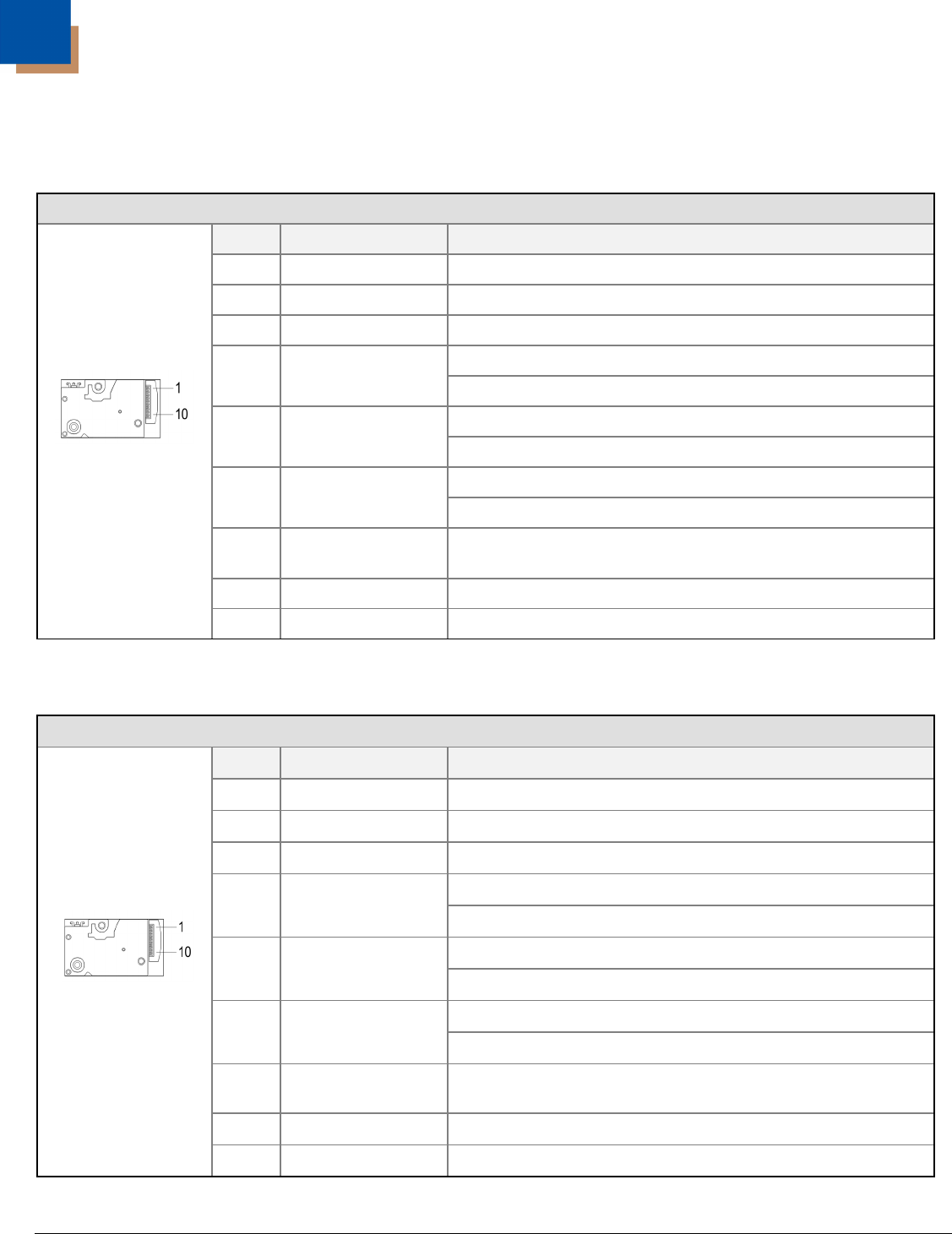
Scan Engine Terminations
IS4813 Engine Connections
10-Pin ZIF Connector
Pin Signal Name Function
1 No Connect No Connect
2 Power, V
CC
3.3V ± 0.3V
3 No Connect No Connect
High = Laser OFF
4 Laser Enable*
Low = Laser ON, only if pin 5 (scan enable) is also Low
High = Engine OFF
5 Scan Enable*
Low = Engine ON
High = Bar
6
Digitized Bar
Pattern, Data Out
Low = Space
7
Start of Scan,
Scan Sense
Level changes from high to low, or low to high, when the
laser changes direction at the start of the scan line.
8 and 9 Ground Power Ground
Figure 16. IS4813
10 No Connect No Connect
IS4815 Engine Connections
10-Pin ZIF Connector
Pin Signal Name Function
1 No Connect No Connect
2 Power, V
CC
5.0V ± 5%
3 No Connect No Connect
High = Laser OFF
4 Laser Enable*
Low = Laser ON, only if pin 5 (scan enable) is also Low
High = Engine OFF
5 Scan Enable*
Low = Engine ON
High = Bar
6
Digitized Bar
Pattern, Data Out
Low = Space
7
Start of Scan,
Scan Sense
Level changes from high to low, or low to high, when the
laser changes direction at the start of the scan line.
8 and 9 Ground Power Ground
Figure 17. IS4815
10 No Connect No Connect
* See Timing Diagrams on page 30.