
Single-Line Laser Scan Engine Integration Guide


Table Of Contents
- IS4813, IS4815, IS4823 and IS4825
- Copyright/Trademarks
- Table Of Contents
- Introduction
- Assembly
- Mounting Specifications
- IS4813 and IS4815 Scan Engine Dimensions
- IS4823 and IS4825 Bracketed (-1 and -2) Dimensions
- IS4823 and IS4825 (-0) Decode Printed Circuit Board Dimensions
- Exit Beam Specifications
- Enclosure Specifications
- Electrostatic Discharge (ESD) Cautions
- Grounding
- Power Supply
- Power Sequencing
- Flex Cables
- Thermal Considerations
- Printed Circuit Board (PCB) Component Clearance
- Magnetic Sensitivity
- Airborne Contaminants and Foreign Materials
- Beam Clearance
- Output Window Properties
- Output Window Coatings
- Output Window Angle
- Minimum Allowable Window Position RequiredTo Avoid Detrimental Internal Reflective Beam Interference at Positive Exit Beam Angle Tolerance
- Minimum Allowable Window Position Required To Avoid Detrimental Internal Reflective Beam Interference at Negative Exit Beam Angle Tolerance
- Scan Engine Field Of View And Depth Of Field
- Descriptions Of IS4823 AND IS4825 Operating Modes
- Serial Configuration Mode
- General Design Specifications
- Detailed Electrical Specifications
- Scan Engine Terminations
- Decode Printed Circuit Board Terminations
- Flex Cable Specifications And Installation Guidelines
- Timing Diagrams
- Bar Code Element Time Calculation
- Regulatory Compliance
- Limited Warranty
- Patents
- Index
- Contact Information
- MANUAL DATE CODE
5
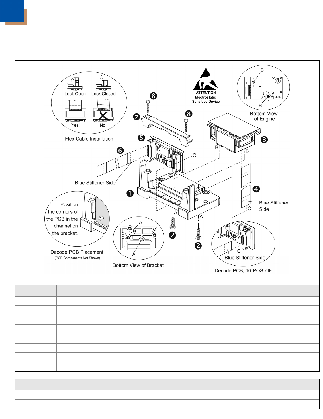
Assembly
IS4823-2 and IS4825-2
Figure 7. IS4823-2/IS4825-2 Assembly
Item Description
Qty.
1 Bracket, Base
1
2 Screw, M1.6 x 35 – 5 mm, Philips Stainless Steel with Patch
2
3 IS4813 or IS4815 Scan Engine
1
4 Flex Cable, 10-POS
1
5 Decode Printed Circuit Board
1
6 Flex Cable, 12-POS
1
7 Bracket, PCB Locking Bar
1
8 Screw, M1.2 – 6 mm, T3, Thread Forming
2
Tools Required
Size
Torx
®
Screw Driver
T3
Phillips Screw Driver
00