
Single-Line Laser Scan Engine Integration Guide


Table Of Contents
- IS4813, IS4815, IS4823 and IS4825
- Copyright/Trademarks
- Table Of Contents
- Introduction
- Assembly
- Mounting Specifications
- IS4813 and IS4815 Scan Engine Dimensions
- IS4823 and IS4825 Bracketed (-1 and -2) Dimensions
- IS4823 and IS4825 (-0) Decode Printed Circuit Board Dimensions
- Exit Beam Specifications
- Enclosure Specifications
- Electrostatic Discharge (ESD) Cautions
- Grounding
- Power Supply
- Power Sequencing
- Flex Cables
- Thermal Considerations
- Printed Circuit Board (PCB) Component Clearance
- Magnetic Sensitivity
- Airborne Contaminants and Foreign Materials
- Beam Clearance
- Output Window Properties
- Output Window Coatings
- Output Window Angle
- Minimum Allowable Window Position RequiredTo Avoid Detrimental Internal Reflective Beam Interference at Positive Exit Beam Angle Tolerance
- Minimum Allowable Window Position Required To Avoid Detrimental Internal Reflective Beam Interference at Negative Exit Beam Angle Tolerance
- Scan Engine Field Of View And Depth Of Field
- Descriptions Of IS4823 AND IS4825 Operating Modes
- Serial Configuration Mode
- General Design Specifications
- Detailed Electrical Specifications
- Scan Engine Terminations
- Decode Printed Circuit Board Terminations
- Flex Cable Specifications And Installation Guidelines
- Timing Diagrams
- Bar Code Element Time Calculation
- Regulatory Compliance
- Limited Warranty
- Patents
- Index
- Contact Information
- MANUAL DATE CODE
19
Serial Configuration Mode
The IS4823/IS4825 can be configured by scanning configuration bar codes
†
or by serial commands sent from
the host device. With serial configuration, each command sent to the engine is the ASCII representation of
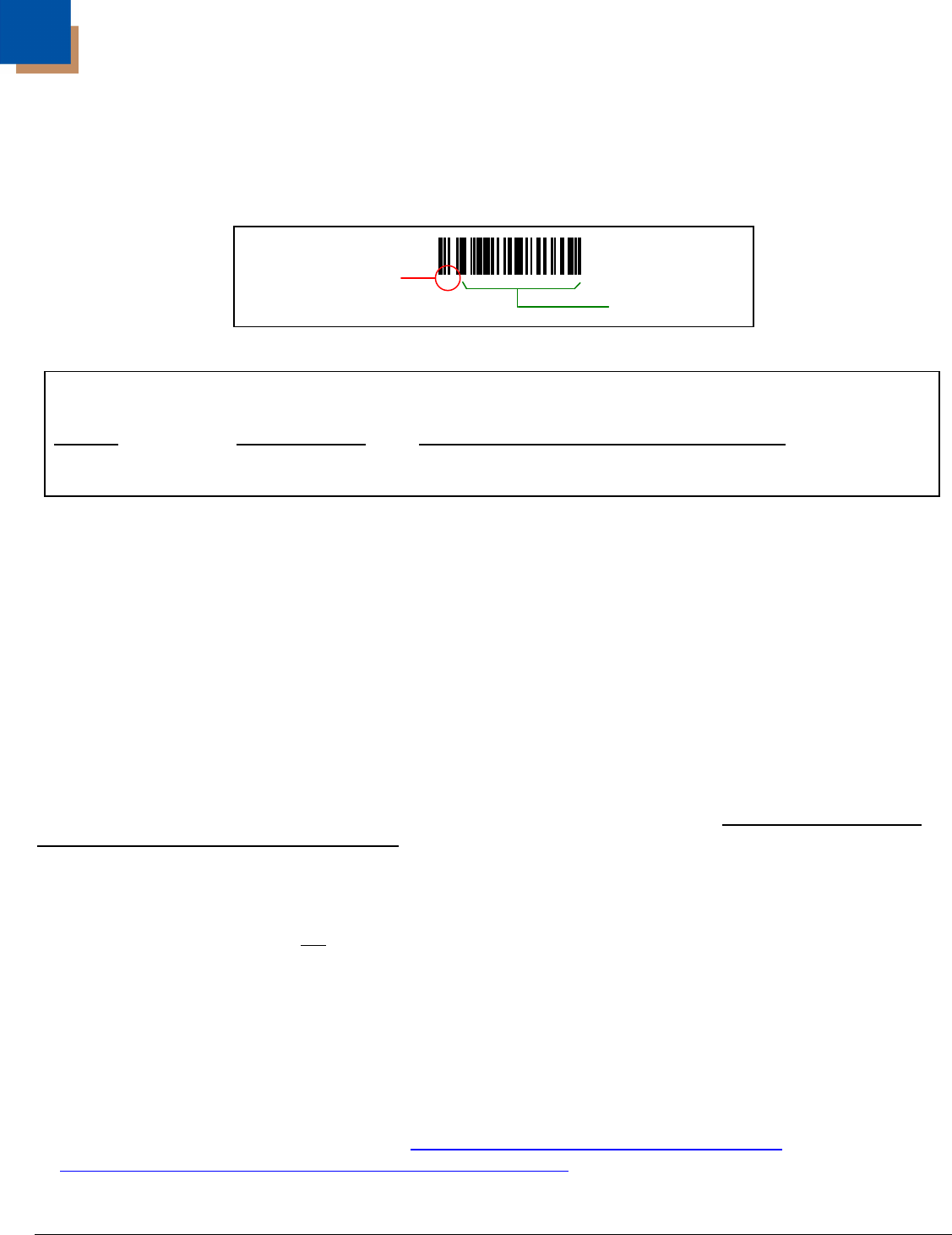
each numeral in the configuration bar code (see
Figure 15). The entire numeric string is framed with an ASCII
[stx] and an ASCII [etx].
Figure 15.
Example 1:
Feature Host Command
String Sent to the Engine -
ASCII Representation (Hexadecimal Values)
Disable Codabar [stx]100104[etx] 02h 31h 30h 30h 31h 30h 34h 03h
[ack]
If the command sent to the engine is valid, the engine will respond with an [ack].
[nak]
If the command sent to the engine is invalid, the engine will respond with a [nak] then automatically
exit serial configuration mode. All the settings chosen in the failed serial configuration session will be lost.
There is a 20-second window between commands. If a 60-second timeout occurs, the engine will
send a [nak].
Enter Serial Configuration Mode
To enter serial configuration mode, send the following command, [stx]999999[etx]. The engine will not scan
bar codes while in serial configuration mode.
Note: Serial configuration mode uses the current Baud Rate, Parity, Stop Bits and Data Bits settings that
are configured in the engine. The default settings of the engine are 9600 bits-per-second, space parity,
2 stop bits, 7 data bits, and no flow control. If a command is sent to the engine to change any of these
settings, the change will not
take effect until after serial configuration mode is exited.
Exit Serial Configuration Mode
To exit serial configuration mode, send the following command, [stx]999999[etx]. The engine will respond
with an [ack].
† Configuration bar codes are located in the MetroSelect Single-Line Guide, PN 00-02544
and the
Supplemental MetroSelect Configuration Guide, PN 00-05268
.
³100104
Do Not Include
in the Command
Include in the
Command