
Single-Line Laser Scan Engine Integration Guide


Table Of Contents
- IS4813, IS4815, IS4823 and IS4825
- Copyright/Trademarks
- Table Of Contents
- Introduction
- Assembly
- Mounting Specifications
- IS4813 and IS4815 Scan Engine Dimensions
- IS4823 and IS4825 Bracketed (-1 and -2) Dimensions
- IS4823 and IS4825 (-0) Decode Printed Circuit Board Dimensions
- Exit Beam Specifications
- Enclosure Specifications
- Electrostatic Discharge (ESD) Cautions
- Grounding
- Power Supply
- Power Sequencing
- Flex Cables
- Thermal Considerations
- Printed Circuit Board (PCB) Component Clearance
- Magnetic Sensitivity
- Airborne Contaminants and Foreign Materials
- Beam Clearance
- Output Window Properties
- Output Window Coatings
- Output Window Angle
- Minimum Allowable Window Position RequiredTo Avoid Detrimental Internal Reflective Beam Interference at Positive Exit Beam Angle Tolerance
- Minimum Allowable Window Position Required To Avoid Detrimental Internal Reflective Beam Interference at Negative Exit Beam Angle Tolerance
- Scan Engine Field Of View And Depth Of Field
- Descriptions Of IS4823 AND IS4825 Operating Modes
- Serial Configuration Mode
- General Design Specifications
- Detailed Electrical Specifications
- Scan Engine Terminations
- Decode Printed Circuit Board Terminations
- Flex Cable Specifications And Installation Guidelines
- Timing Diagrams
- Bar Code Element Time Calculation
- Regulatory Compliance
- Limited Warranty
- Patents
- Index
- Contact Information
- MANUAL DATE CODE
7
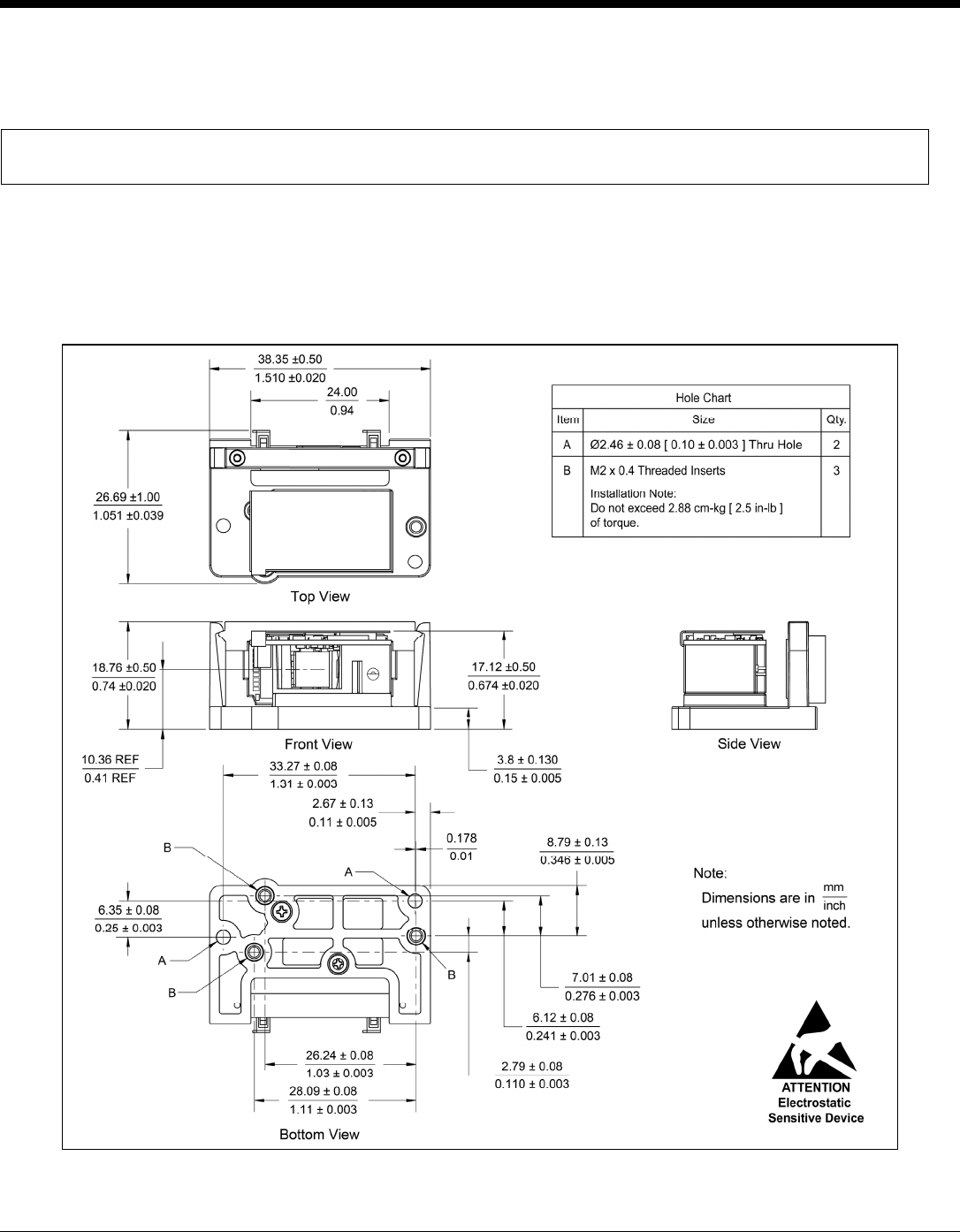
IS4823 and IS4825 Bracketed (-1 and -2) Dimensions
The engine bracket has three M2 x 0.4 threaded inserts on the bottom for mounting the assembly with screws.
Two through holes are also provided as an alternative mounting method.
Warning: The limited warranty (on page 37) is void if the following recommendations are not adhered to
when mounting the IS4800 series laser scan engine.
When securing the engine by utilizing the three M2 threaded inserts:
• Use M2 x 0.4 Phillips Pan Head, Type AB, Steel, Zinc Clear or equivalent screws.
• Do not exceed 2.88 cm-kg [ 2.5 in-lb ] of torque when securing the engine assembly to the host.
• Use a minimum mount thickness of 3 mm.
• Use safe ESD practices when handling and mounting the engine assembly.
Figure 9. IS4823/IS4825 Bracketed (-1 and -2) Dimensions
Specifications are for reference only and are subject to change without notice.