IS3480 QuantumE ® Scan Engine Installation and User’s Guide
Copyright © 2008 by Metrologic Instruments, Inc. All rights reserved. No part of this work may be reproduced, transmitted, or stored in any form or by any means without prior written consent, except by reviewer, who may quote brief passages in a review, or provided for in the Copyright Act of 1976. Trademarks Metrologic is a registered trademark of Metrologic Instruments, Inc. Products identified in this document are hereby acknowledged as trademarks, registered or otherwise, of Metrologic Instruments, Inc.
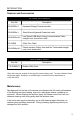
TABLE OF CONTENTS Introduction Product Overview ............................................................................................. 1 Scanner and Accessories................................................................................. 2 Maintenance..................................................................................................... 3 Scanner Components....................................................................................... 4 Cable Removal.........................
TABLE OF CONTENTS Depth of Field by Bar Code Element Width Normal Scan Zone ..................................................................................... 23 Reduced Scan Zone................................................................................... 24 IR Activation Range........................................................................................ 25 Troubleshooting Guide .......................................................................................
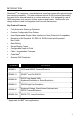
INTRODUCTION ® QuantumE is a miniature, omni-directional scanning engine with optional singleline scanning capability. The self-contained device is fully enclosed eliminating the need for an external window or custom enclosure. It is designed for use in OEM equipment such as price lookup systems and kiosks. QuantumE s slim design makes it ideal for integration and use with flat-screens.
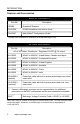
INTRODUCTION Scanner and Accessories BASIC KIT COMPONENTS Part No. Description IS3480 QuantumE Scanner 00-02026 IS3480 Installation and User’s Guide * 00-02407 MetroSelect® Configuration Guide * * Guides also available for download at www.metrologic.com. OPTIONAL ACCESSORIES Part No. Description AC to DC Power Transformer - Regulated 5.2VDC @ 1A output.
INTRODUCTION Scanner and Accessories OPTIONAL ACCESSORIES Part No. Description 59-59002x-3 Keyboard Wedge PowerLink cable 59-59020x-3 Stand Alone Keyboard PowerLink cable 59-59235x-N-3 Low Speed USB Non-Locking Communication Cable straight cord, short strain relief 35-35959 Utility Flex Cable 59-59249x-N-3 Communication Cable, Host end Not Terminated straight cord, short strain relief REPLACEMENT PARTS Part No.
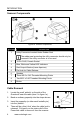
INTRODUCTION Scanner Components Figure 1a. Scanner Components ITEM NO. 1 DESCRIPTION Utility Connector Located Under Rubber Seal The rubber seal protecting the utility connector should only be removed if the utility connector is to be used. 2 10-Pin RJ45, Female Socket 3 Blue, White and Yellow LED Indicators 4 Red Output Window (Laser Aperture) 5 Pin Hole for Cable Release 6 Speaker 7 Three M2.5 x 0.45 Threaded Mounting Points 8 Two M2.5 x 0.
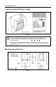
INTRODUCTION Caution and Serial Number Labels Figure 2. Caution To maintain compliance with applicable standards, all circuits connected to the scanner must meet the requirements for SELV (Safety Extra Low Voltage) according to EN/IEC 60950-1. To maintain compliance with standard CSA C22.2 No. 60950-1/UL 60950-1 and norm EN/IEC 60950-1, the power source should meet applicable performance requirements for a limited power source. Mounting Specifications Figure 3.
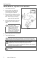
INSTALLATION RS232, RS232 TTL, Light Pen or Laser Emulation 1. Turn off the host device. 2. Plug the male 10-pin RJ45 end of the PowerLink cable into the 10-pin socket on the IS3480. 3. Connect the 9-pin female end of the PowerLink cable to the host device. Note: Skip to step 6 if receiving power from the host device. 4. Plug the external power supply into the power jack on the PowerLink cable. Check the AC input requirements of the power supply to make sure the voltage matches the AC outlet.
INSTALLATION RS485 or OCIA 1. Turn off the host device. 2. Plug the male 10-pin RJ45 end of the MVC cable into the 10-pin socket on the IS3480. 3. Connect the other end of the MVC cable to the host device. 4. Turn on the host device. Figure 5. When the scanner first receives power, the blue LED will turn on; the scanner will simultaneously beep once and flash the white LED. Plugging the scanner into the serial port of the PC does not guarantee that scanned information will appear at the PC.
INSTALLATION Keyboard Wedge 1. Turn off the host device. 2. Plug the male 10-pin RJ45 end of the PowerLink cable into the 10-pin socket on the IS3480. 3. Disconnect the keyboard from the host device. 4. Connect the “Y” end of the PowerLink cable to the keyboard and the keyboard port on the host device. If necessary, use the male/female adapter cable supplied with the scanner for proper connections. 5. Plug the external power supply into the power jack on the PowerLink cable.
INSTALLATION Stand-Alone Keyboard 1. Turn off the host device. 2. Plug the male 10-pin RJ45 end of the PowerLink cable into the 10-pin socket on the IS3480. 3. Connect the other end of the PowerLink cable to the keyboard port on the host device. 4. Plug the external power supply into the power jack on the PowerLink cable. Check the AC input requirements of the power supply to make sure the voltage matches the AC outlet. The outlet must be located near the equipment and be easily accessible. 5.
INSTALLATION Low Speed USB (Integrated) 1. Turn off the host device. 2. Plug the male 10-pin RJ45 end of the USB PowerLink cable into the 10-pin socket on the IS3480. 3. Plug the other end of the USB interface cable into the host device’s USB port. 4. Turn on the host device. As a default, the IS3480-38 leaves the factory with USB Keyboard Emulation Mode enabled.
INSTALLATION Notes for Laser Emulation IS3480-104 Only The IS3480-104 leaves the factory with the Laser Emulation Mode enabled. If the Recall Defaults bar code is scanned while reconfiguring the scanner, the laser emulation mode will no longer be enabled. Scan the following bar code to re-enable the laser emulation interface. This feature is only supported for IS3480-104 models.
SCANNER OPERATION Configurable Primary and Secondary Scan Pattern Modes There are two configurable scan pattern modes available with the IS3480. • The primary scan pattern mode is the default scan pattern active when the scanner starts. • The secondary scan pattern mode is activated by pressing the button located on the side of the scanner. This mode is also referred to as the button mode.
SCANNER OPERATION Configurable Button Functions SECONDARY SCAN PATTERN BUTTON CLICK MODE WITH CODEGATE ENABLED For illustration purposes the unit’s primary scan pattern has been set to all scan lines (omnidirectional reading) and the secondary pattern has been set to single-line (menu reading) with a 10 second button click timeout configured. 1. The primary scan pattern is active when the scanner starts. 2. To activate the secondary scan pattern, press and release the button. 3.
SCANNER OPERATION Configurable Button Functions SECONDARY SCAN PATTERN BUTTON CLICK MODE WITH CODEGATE DISABLED For illustration purposes the unit’s primary scan pattern has been set to all scan lines (omnidirectional reading) and the secondary pattern has been set to single-line (menu reading) with a 10 second button click timeout configured. 14 www.metrologic.com 1. The primary scan pattern is active when the scanner starts. 2. To activate the secondary scan pattern, press and release the button.
SCANNER OPERATION Configurable Button Functions SECONDARY SCAN PATTERN BUTTON HOLD MODE WITH CODEGATE ENABLED For illustration purposes the unit’s primary scan pattern has been set to all scan lines (omnidirectional reading) and the secondary pattern has been set to single-line (menu reading) with a 10 second button click timeout configured. 1. The primary scan pattern is active when the scanner starts. 2. To activate the secondary scan pattern, press and hold the button. 3.
SCANNER OPERATION Configurable Button Functions SECONDARY SCAN PATTERN BUTTON HOLD MODE WITH CODEGATE DISABLED For illustration purposes the unit’s primary scan pattern has been set to all scan lines (omnidirectional reading) and the secondary pattern has been set to single-line (menu reading) with a 10 second button click timeout configured. 16 www.metrologic.com 1. The primary scan pattern is active when the scanner starts. 2. To activate the secondary scan pattern, press and hold the button. 3.
SCANNER OPERATION Sweet Spot Mode The sweet spot mode is used to determine where the maximum read rate area or “sweet spot” is located for a specific bar code type. When activated this mode provides visual and audible feedback indicating how the scanner is scanning.
SCANNER OPERATION Audible Indicators When the IS3480 is in operation, it can provide audible feedback. These sounds indicate the status of the scanner. Eight settings are available for the tone of the beep (normal, six alternate tones and no tone). For instruction on how to change the tone of the beeper, refer to the MetroSelect Configuration Guide (00-02407).
SCANNER OPERATION Visual Indicators There are four LEDs located on the top of the IS3480. When the scanner is on, the flashing or constant illumination of the LEDs indicates the status of the current scan and the scanner. No LEDs The LEDs will not be illuminated if the scanner is not receiving power from the host or transformer. They are also not illuminated when all lasers are turned off for any reason. Steady Blue When the laser is active, the blue LED is illuminated.
SCANNER OPERATION Failure Mode Indicators Flashing Blue and One Razzberry Tone This indicates that the scanner has experienced a laser subsystem failure. Return the unit to an authorized service center for repair. Flashing Blue and White and Two Razzberry Tones This indicates that the scanner has experienced a motor failure. Return the unit to an authorized service center for repair.
SCANNER OPERATION Depth of Field Specifications* Normal Scan Zone Specifications are based on a 0.33 mm (13 mil) bar code. Figure 9. Normal Depth of Field * All specifications are subject to change without notice.
SCANNER OPERATION Depth of Field Specifications* Reduced Scan Zone Specifications are based on a 0.33 mm (13 mil) bar code. Figure 10. Reduced Depth of Field * All specifications are subject to change without notice. 22 www.metrologic.
SCANNER OPERATION Depth of Field by Bar Code Element Width* Normal Scan Zone MINIMUM BAR CODE ELEMENT WIDTH A B C D E F mm .13 .15 .19 .25 .33 .66 mils 5.2 5.7 7.5 10 13 26 Figure 11. Normal Scan Zone by Bar Code Element Width * All specifications are subject to change without notice.
SCANNER OPERATION Depth of Field by Bar Code Element Width* Reduced Scan Zone MINIMUM BAR CODE ELEMENT WIDTH A B C D E F mm .13 .15 .19 .25 .33 .66 mils 5.2 5.7 7.5 10 13 26 Figure 12. Reduced Scan Zone by Bar Code Element Width * All specifications are subject to change without notice. 24 www.metrologic.
SCANNER OPERATION IR Activation Range* QuantumE’s default power save mode† is Laser OFF. This power save mode turns the laser off after a configured period of non-use. Any movement detected by the IR in the activation area will cause the scanner to exit power save mode. The laser will automatically turn back on preparing the scanner for bar code recognition, decoding and transmission. Figure 13. IR Activation Range * All specifications are subject to change without notice.
TROUBLESHOOTING GUIDE The following guide is for reference purposes only. Contact a Metrologic representative at 1-800-ID-METRO or 1-800-436-3876 to preserve the limited warranty terms on page 46. Symptoms Possible Cause(s) Solution All Interfaces The unit has no LEDs, beeper or motor spin. No power is being supplied to the scanner. Check the transformer, outlet and power strip. Make sure the cable is plugged into the scanner. The unit has no LEDs and/or beeper.
TROUBLESHOOTING GUIDE Symptoms Possible Cause(s) Solution The scanner is configured to support some form of host handshaking but is not receiving the signal. If the scanner is setup to support ACK/NAK, RTS/CTS, XON/XOFF or D/E, verify that the host cable and host are supporting the handshaking properly. The bar code may have been printed incorrectly. Check if it is a check digit, character or border problem. The scanner is not configured correctly for the type of bar code.
TROUBLESHOOTING GUIDE Symptoms Possible Cause(s) Solution RS232 Only The unit powers up OK and scans OK but does not communicate properly to the host. The com port at the host is not working or is not configured properly. The cable is not connected to the proper com port. Check to make sure that the baud rate and parity of the scanner and the communication port match and that the program is looking for RS232 data. The com port is not operating properly.
DESIGN SPECIFICATIONS IS3480 Operational Light Source: Laser Power: Normal Depth of Field: Reduced Depth of Field: Visible Laser Diode (VLD) @ 650 nm 1.1 mW 25 mm - 280 mm (1"- 11") 25 mm - 150 mm (1"- 6") 0.33 mm (13 mil) bar code Omni Scan Scan Speed: No. of Scan Lines: 1650 scan lines per second 20 Single-Line Scan Speed: No. of Scan Lines: 80 scan lines per second 1 Raster Scan Speed: No. of Scan Lines Motor Speed: Min Bar Width: 4 5000 RPM 0.127 mm (5.
DESIGN SPECIFICATIONS IS3480 Mechanical Width: 63 mm (2.48") Depth: 50 mm (1.97") Height: 68 mm (2.68") Weight: 6 oz (170 g) Electrical Voltage Supply: Operating Power: Standby Power: 5VDC ± 0.25V 1.375 W 1.0 W Operating Current: 275 mA typical at 5VDC Standby Current: 200 mA typical at 5VDC DC Transformers: Class II; 5.2VDC @ 1A For regulatory compliance information, see pages 43 – 45.
APPLICATIONS AND PROTOCOLS The model number on each scanner includes the scanner number and factory default communications protocol.
DEFAULT SETTINGS - COMMUNICATION PARAMETERS Many functions of the scanner can be "configured" - that is enabled or disabled. The scanner is shipped from the factory configured to a set of default conditions. The default parameter of the scanner has an asterisk ( * ) in the charts on the following pages. If an asterisk is not in the default column then the default setting is Off or Disabled. Not every interface supports every parameter.
DEFAULT SETTINGS - COMMUNICATION PARAMETERS RS232* PARAMETER DEFAULT OCIA USB OR RS232 TTL LIGHT RS485 KBW PEN LASER EMULATION * Expanded ID “]e0” RSS Limited Enable RSS Limited ID “]e0” * RSS Limited App ID “01” * RSS Limited Check Digit * Bars High as Code 39 * Spaces High as Code 39 Bars High as Scanned Spaces High as Scanned DTS/SIEMENS * DTS/NIXDORF NCR F NCR S Poll Light Pen Source Beeper Tone Normal Beep/Transmit Sequence Before Transmit Communication Timeout None Razzberry To
DEFAULT SETTINGS - COMMUNICATION PARAMETERS RS232* PARAMETER DEFAULT OCIA USB Transmit UPC-A Check Digit * Transmit UPC-E Check Digit Expand UPC-E Convert UPC-A to EAN-13 Transmit Lead Zero on UPC-E Convert EAN-8 to EAN-13 Transmit UPC-A Number System * Transmit UPC-A Manufacturer ID# * Transmit UPC-A Item ID# * Transmit Codabar Start/Stop Characters CLSI Editing (Enable) Transmit Mod 43 Check Digit on Code 39 Transmit Code 39 Stop/Start Characters Transmit Mod 10/ITF Transmit MSI-Plessey Check Ch
DEFAULT SETTINGS - COMMUNICATION PARAMETERS RS232* PARAMETER DEFAULT OCIA USB OR RS232 TTL LIGHT RS485 KBW PEN LASER EMULATION Nixdorf ID LRC Enabled UPC Prefix UPC Suffix Transmit AIM ID Characters STX Prefix ETX Suffix Carriage Return * Line Feed - disabled by default in KBW * Tab Prefix Tab Suffix “DE” Disable Command “FL” Laser Enable Command DTR Handshaking Support RTS/CTS Handshaking * Character RTS/CTS Message RTS/CTS XON/XOFF Handshaking ACK/NAK Two Digit Supplements as code 39 as cod
DEFAULT SETTINGS - COMMUNICATION PARAMETERS RS232* PARAMETER DEFAULT OCIA USB Supplements are not Required * Two Digit Redundancy * OR RS232 TTL LIGHT LASER RS485 KBW PEN EMULATION Five Digit Redundancy 100 msec to Find Supplement Programmable in 100msec steps (MAX 800 msec) * as code 39 Coupon Code 128 Programmable Code Lengths 7 avail. Programmable Prefix Characters 10 avail. Programmable Suffix Characters 10 avail.
UPGRADING THE FIRMWARE The IS3480 is part of Metrologic's line of scanners with flash upgradeable firmware. The upgrade process requires, a new firmware file supplied to the customer by a customer service representative and Metrologic's MetroSet2 software . A personal computer running Windows 95 or greater with an available RS232 serial or USB port is required to complete the upgrade. Do not use the standard cable supplied with Keyboard Wedge or RS485 IS3480 interface kits for firmware upgrades.
SCANNER AND CABLE TERMINATIONS Scanner Pinout Connections The IS3480 scanner interfaces terminate to a 10-pin modular socket. The serial number label indicates the interface enabled when the scanner is shipped from the factory. Figure 14.
SCANNER AND CABLE TERMINATIONS Figure 15.
SCANNER AND CABLE TERMINATIONS Figure 16. Figure 17. Zero Insertion Force Connector (ZIF), 6-pin Utility Connector Pin 1 40 Function Aux +5V: Power out. Can supply up to 100mA @ 5V. 2 Good Read: Open-collector output. Low-going 20mA output for duration of 32 ms at a baud rate of 9600. Represents a successful bar code read. Can be used to drive an external LED. Requires an external current limiting resistor of 182 ohms. 3 Aux Beeper: Open-collector output.
SCANNER AND CABLE TERMINATIONS Cable Connector Configurations (Host End) “Standard” PowerLink Cable 53-53000x-3 coiled or 59-59000x-3 straight Pin Function 1 Shield Ground 2 RS232 Transmit Output 3 RS232 Receive Input 4 DTR Input/Light Pen Source 5 Power/Signal Ground 6 Light Pen Data 7 CTS Input 8 RTS Output 9 +5VDC 9 5 6 1 9-Pin D-Type Connector USB Power/Communication Cable 59-59235x-N-3 Pin Function 1 PC +5V/V_USB 2 D- 3 D+ 4 Ground USB Non-Locking Shield Shield Stand
SCANNER AND CABLE TERMINATIONS Cable Connector Configurations (Host End) Keyboard Wedge PowerLink Cable 59-59002x-3 Pin 1 2 3 4 5 Pin 1 2 3 4 5 6 Function Keyboard Clock Keyboard Data No Connect Power Ground +5 Volts DC Function PC Data No Connect Power Ground +5 Volts DC PC Clock No Connect 5-Pin DIN, Female 6-Pin DIN, Male Metrologic will supply an adapter cable with a 5-pin DIN male connector on one end and a 6-pin mini DIN female connector on the other.
REGULATORY COMPLIANCE Safety ITE Equipment IEC 60950-1, EN 60950-1 Laser Laser Class 1: IEC 60825-1:1993+A1+A2, EN 60825-1:1994+A1+A2 Caution Use of controls or adjustments or performance of procedures other than those specified herein may result in hazardous laser light exposure. Under no circumstances should the customer attempt to service the laser scanner. Never attempt to look at the laser beam, even if the scanner appears to be nonfunctional.
REGULATORY COMPLIANCE EMC Emissions FCC Part 15, ICES-003, CISPR 22, EN 55022 Immunity CISPR 24, EN 55024 NOTE: Immunity performance is not guaranteed for scanner cables greater than 3 meters in length when fully extended. Changes or modifications not expressly approved by the party responsible for compliance could void the user’s authority to operate the equipment. Class A Devices The following is applicable when the scanner cable is greater in length than 3 meters (9.
REGULATORY COMPLIANCE EMC Changes or modifications not expressly approved by the party responsible for compliance could void the user’s authority to operate the equipment. Standard Europeo Attenzione Questo e’ un prodotto di classe A. Se usato in vicinanza di residenze private potrebbe causare interferenze radio che potrebbero richiedere all’utilizzatore opportune misure. Attention Ce produit est de classe “A”. Dans un environnement domestique, ce produit peut être la cause d’interférences radio.
LIMITED WARRANTY The IS3480 QuantumE® scanners are manufactured by Metrologic at its Suzhou, China facility. The IS3480 QuantumE® scanners have a two (2) year limited warranty from the date of manufacture. Metrologic warrants and represents that all IS3480 QuantumE® scanners are free of all defects in material, workmanship and design, and have been produced and labeled in compliance with all applicable U.S.
PATENTS Patent Information This METROLOGIC product may be covered by, but not limited to, one or more of the following U.S. Patents: U.S. Patent No.
INDEX A F AC ....................................... 2, 6–10 Accessories ...............................2, 3 Adapter..........................................8 Audible Indicator.. 12, 18–20, 26–28 Failure Modes...................................... 20 Firmware ..................................... 37 Flash ROM.............................. 1, 37 B H Bar Code ............. 18–20, 26–28, 29 Bar Width.....................................29 Beep .................... 18, 19, 20, 26–28 Blue LED ............
INDEX M S Maintenance..................................3 Manual............................... 2, 18, 31 Mode of Operation Button ......................................17 Primary ..............................12–17 Secondary..........................12–17 Sweet Spot Mode ..............17, 36 Motor Speed................................29 Mounting Specifications ................5 Safety.................................... 43, 45 Scan Lines .................................. 29 Scan Pattern ................
50 www.metrologic.
October 2008 0 0 - 0 2 0 2 6G