METROLOGIC INSTRUMENTS, INC.
Copyright © 2008 by Metrologic Instruments, Inc. All rights reserved. No part of this work may be reproduced, transmitted, or stored in any form or by any means without prior written consent, except by reviewer, who may quote brief passages in a review, or provided for in the Copyright Act of 1976. Trademarks Metrologic is a registered trademark of Metrologic Instruments, Inc. Products identified in this document are hereby acknowledged as trademarks, registered or otherwise, of Metrologic Instruments, Inc.
TABLE OF CONTENTS INTRODUCTION Product Overview ............................................................................................. 1 Key Product Features....................................................................................... 1 Applications and Protocols ............................................................................... 2 Scanner and Accessories................................................................................. 3 Design Specifications ....................
TABLE OF CONTENTS Visual Indicators ............................................................................................. 23 Failure Modes................................................................................................. 24 Depth of Field by Minimum Bar Code Element Width .................................... 25 IR Activation Range........................................................................................ 26 MAINTENANCE Daily Maintenance...................................
INTRODUCTION PRODUCT OVERVIEW The IS1650 is a high performance area imaging bar code scanner that utilizes a high-resolution CMOS imaging sensor for unrivaled image quality. The IS1650 is the choice of 2D imaging scanners that delivers superior performance for presentation and fixed-mount applications. The IS1650 employs Omniplanar, Inc.’s SwiftDecoder™ software, for reliable decoding of all 1D and 2D bar code symbologies.
INTRODUCTION APPLICATIONS AND PROTOCOLS The model number on each scanner includes the scanner number and factory default communications protocol.
INTRODUCTION SCANNER AND ACCESSORIES BASIC KIT Part # IS1650 Description Area Imaging Bar Code Scanner 00-02544 MetroSelect® Single-Line Configuration Guide* 00-02281 Area Imaging Supplemental Configuration Guide* 00-02287 IS1650 Series Area Imaging Bar Code Scanner Installation and User’s Guide* * Also available for download on the Metrologic website - www.metrologic.com OPTIONAL ACCESSORIES Part # Description AC to DC Power Transformer Regulated 5.2VDC @ 1 AMP output.
INTRODUCTION SCANNER AND ACCESSORIES OPTIONAL ACCESSORIES Part # Description IS1650 Scanner Interface Specific Cables 59-59000-3 RS232 PowerLink Cable with Built in Power Jack, straight, black 54-54002-3 Keyboard Wedge PowerLink Cable with Adapter Cable, straight, black 54-54020-3 Stand Alone Keyboard PowerLink Cable, straight, black 59-59313-N-3 MVC-3M106S-IB9 USB Power/Communication Cable, straight, black Metrologic Voltage Converter (MVC) Cable* ±12VDC to +5.
INTRODUCTION SCANNER AND ACCESSORIES OPTIONAL ACCESSORIES Part # Description 00-02001 IS1650 Series Stand Installation Guide 46-00710 Flex Stand, Kit Flex Stand, Kit Components a. Stand Base ...............................................................................Qty. 1 b. Flexible Shaft............................................................................Qty. 1 c. Flexible Shaft Cover ................................................................Qty. 1 d. Scanner Cradle.................
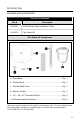
INTRODUCTION DESIGN SPECIFICATIONS IS1650 DESIGN SPECIFICATIONS OPERATIONAL Light Source: LED 645 nm Pulse Duration: 1 ms to 8 ms Maximum Output of an Osram LED: Depth of Scan Field: Field of View: Minimum Bar Width: Infrared Activation: Decode Capability: Maximum 85 mA emits 3,120 mlm 0 mm – 254 mm (0" – 10") for 0.330 mm (13 mil) Bar Code at Default Setting 49 mm W x 19 mm H (1.9" W x 0.8"H) at 20 mm (0.8") 264 mm x 106 mm (10.4"W x 4.2" H) at 280 mm (11.0") 0.127 mm (5.
INTRODUCTION DESIGN SPECIFICATIONS (CONT.) IS1650 DESIGN SPECIFICATIONS ELECTRICAL Input Voltage: 5.0VDC ± 0.25V Peak = 2 W (Typical) Power: Operating = 1.65 W (Typical) Idle / Standby = 800 mW (Typical) Peak = 400 mA (Typical) Current: Operation = 330 mA (Typical) Idle / Standby = 160 mA (Typical) DC Transformer: Class 2; 5.
BASE MODEL CHARACTERISTICS IS1650 SCANNER Components Figure 1.
BASE MODEL CHARACTERISTICS IS1650 SCANNER Dimensions Figure 2. Scanner Dimensions Figure 3. M3 Mounting Hole Dimensions Caution: The depth of each mounting hole is 12 mm (0.5"). For fixed mount, the mounting screws should not be over-tightened or go deeper than 10 mm (0.4") passing the bottom surface of the unit. Going further may cause serious damage to the unit and void the manufacturer warranty.
BASE MODEL CHARACTERISTICS IS1650 SCANNER Caution and Serial Number Labels Each scanner has a label located on the bottom of the unit, as well as text embedded into the bottom casing. This label provides the unit’s model number, date of manufacture, serial number, CE and caution information. The following figure gives an example of the label/text and their location. Figure 4.
INSTALLATION THE POWERLINK CABLE Connecting Important: If the PowerLink cable is not fully ‘latched’, the unit can power intermittently. Figure 5. Figure 6. Disconnecting Before removing the cable from the scanner, Metrologic recommends that the power on the host system is off and the power supply has been disconnected from the PowerLink cable. Figure 7. Releasing the PowerLink Cable 1. Locate the small ‘pin-hole’ on the bottom of the unit near the cable. 2.
INSTALLATION CABLE INSTALLATION (INTERFACE SPECIFIC) RS232 IS1650-14 1. Turn off the host device. 2. Plug the male 10-pin RJ45 end of the PowerLink cable into the 10-pin socket on the IS1650. There will be an audible click when the connector lock engages. 3. Connect the 9-pin D-type connector of the communication cable to the proper COM port of the host device. 4. Plug the power supply into the power jack on the PowerLink cable.
INSTALLATION CABLE INSTALLATION (INTERFACE SPECIFIC) Keyboard Wedge IS1650-47 1. Turn off the host device. 2. Plug the 10-pin RJ45 male end of the PowerLink cable into 10-pin socket on the IS1650. There will be an audible click when the connector lock engages. 3. Disconnect the keyboard from the host device. 4. Connect the “Y” ends of the communication cable to the keyboard and keyboard port on the host device.
INSTALLATION CABLE INSTALLATION (INTERFACE SPECIFIC) Stand Alone Keyboard IS1650-47 1. Turn off the host device. 2. Plug the male 10-pin RJ45 end of the PowerLink cable into the 10-pin socket on the IS1650. There will be an audible click when the connector lock engages. 3. Plug the other end of the communication cable into the host’s keyboard port. 4. Plug the external power supply (required) into the power jack on the PowerLink cable.
INSTALLATION CABLE INSTALLATION (INTERFACE SPECIFIC) IBM 46xx RS485 IS1650-106 1. Turn off the host device. 2. Plug the male 10-pin RJ45 end of the MVC cable into the 10-pin socket on the IS1650. There will be an audible click when the connector lock engages. 3. Connect the other end of the MVC cable to the host device. 4. Turn on the host device. 5. The IS1650 will start to initialize. All LEDs (yellow, white, and blue) will light for approximately two seconds then start to alternately flash.
INSTALLATION CABLE INSTALLATION (INTERFACE SPECIFIC) Integrated USB: Low Speed IS1650-38 Full Speed IS1650-106 1. Turn off the host device. 2. Plug the male 10-pin RJ45 end of the USB cable into the 10-pin socket on the IS1650. There will be an audible click when the connector lock engages. 3. Plug the USB type A end (locking with power or non-locking, depending upon host setup) of the USB cable into the host’s USB port. 4. Turn on the host device. 5. The IS1650 will start to initialize.
INSTALLATION FLEX STAND INSTALLATION (OPTIONAL) Metrologic provides two #8 wood screws for securing the stand base to the counter top. The following figure provides the pilot hole dimensions for securing the stand base. Figure 13.
INSTALLATION FLEX STAND INSTALLATION (OPTIONAL) Figure 14.
SCANNER CONFIGURATION CONFIGURATION MODES The IS1650 Series scanner has three modes of configuration. • Bar Codes The IS1650 can be configured by scanning the bar codes included in the Metrologic Single-Line Configuration Guide (MLPN 00-02544) or the Supplemental Configuration Guide (MLPN 00-02281). These manuals can be downloaded FREE of charge from Metrologic’s website (www.metrologic.com).
SCANNER CONFIGURATION The IS1650 FocusE is part of Metrologic's line of scanners with flash upgradeable firmware. The upgrade process requires a new firmware file supplied to the customer by a customer service representative and Metrologic's MetroSet2 software . A personal computer running Windows 95 or greater with an available RS232 serial or USB port is also required to complete the upgrade. PowerLink Cable #54-54014 is required when using RS232 for the upgrade process.
SCANNER OPERATION MODES OF OPERATION* Presentation Mode, Fixed-Mount or In-Stand (Default) 1. The IR detects an object in the IR activation range and the scanner’s light output automatically starts to flash as it attempts to scan the bar code. 2. The scanner continuously attempts to scan the bar code until either it succeeds or the bar code is removed from the scanner’s field of view. 3.
SCANNER OPERATION AUDIBLE INDICATORS When the IS1650 is in operation, it provides audible feedback. These sounds indicate the status of the scanner. Eight settings are available for the tone of the beep (normal, 6 alternate tones and no tone). To change the tone, refer to the MetroSelect Single-Line Configuration Guide (MLPN 00-02544) or MetroSet2’s help files. One Beep When the scanner successfully reads a bar code, it will beep once and the white LED will turn on indicating data is being transmitted.
SCANNER OPERATION VISUAL INDICATORS The IS1650 has three LED indicators (yellow, white and blue) located on the top of the scanner. When the scanner is on, the flashing or constant activity of the LEDs indicates the status of the current scan and the scanner. No LEDs are Illuminated The LEDs will not illuminate if the scanner is not receiving power from the host or transformer. The scanner is in stand-by mode. Present a bar code to the scanner and the blue LED will turn on when the IR detects the object.
SCANNER OPERATION FAILURE MODES Long Razzberry Tone – During Power Up Failed to initialize or configure the scanner. If the scanner does not respond after reprogramming, return the scanner for repair. Short Razzberry Tone – During Scanning An invalid bar code has been scanned when in configuration.
SCANNER OPERATION DEPTH OF FIELD BY MINIMUM BAR CODE ELEMENT WIDTH MINIMUM BAR CODE ELEMENT WIDTH 1D PDF A B C D E F G mm .132 .191 .254 .330 .533 .254 .381 mils 5.2 7.5 10.4 13 21 10 15.9 Figure 17. Depth of Field by Minimum Bar Code Element Width Specifications are subject to change without notice.
SCANNER OPERATION IR ACTIVATION RANGE The IS1650 has a built in object detection sensor that instantly turns on the scanner when an object is presented within the scanner’s IR activation Area. Figure 18. IR Activation Area Specifications are subject to change without notice.
MAINTENANCE DAILY MAINTENANCE Smudges and dirt on the unit's window can interfere with the unit's performance. If the window requires cleaning, use only a mild glass cleaner containing no ammonia. When cleaning the window, spray the cleaner onto a lint free, nonabrasive cleaning cloth then gently wipe the window clean. If the unit's case requires cleaning, use a mild cleaning agent that does not contain strong oxidizing chemicals. Strong cleaning agents may discolor or damage the unit's exterior.
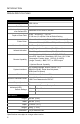
TROUBLESHOOTING GUIDE The following guide is for reference purposes only. Contact a Metrologic representative at 1-800-ID-Metro or 1-800-436-3876 to preserve the limited warranty terms. All Interfaces IS1650 Series Troubleshooting Symptom / Solution Chart Symptoms Possible Causes Solution No power is being supplied to the scanner. Check transformer, outlet and power strip. Make sure the cable is plugged into the scanner. No power is being supplied to the scanner from the host.
TROUBLESHOOTING GUIDE Symptoms Possible Causes Solution The unit powers The beeper is up, but does not disabled and no tone beep when bar is selected. code is scanned. Enable the beeper and select a tone. The unit powers up, but does not scan and/or beep. The bar code symbology trying to be scanned is not enabled. UPC/EAN, Code 39, interleaved 2 of 5, Code 93, Code 128, Codabar and PDF are enabled by default. Verify that the type of bar code being read has been selected.
TROUBLESHOOTING GUIDE Symptoms The unit beeps at some bar codes and NOT for others of the same bar code symbology. The unit scans the bar code but there is no data. Possible Causes Solution The bar code may have been printed incorrectly. Check if it is a check digit/character/or border problem. The scanner is not configured correctly for this type of bar code. Check if check digits are set properly. The minimum symbol length setting does not work with the bar code.
TROUBLESHOOTING GUIDE Symptoms Possible Causes Solution The unit is transmitting each character twice. The configuration is not set correctly. Increase interscan code delay setting. Adjust whether the F0 break is transmitted. It may be necessary to try this in both settings. Alpha characters show as lower case. The computer is in Caps Lock mode. Enable Caps Lock detect setting of the scanner to detect if the PC is operating in Caps Lock. Everything works except for a couple of characters.
DEFAULT SETTINGS Many functions of the scanner can be “configured” – that is, enabled or disabled. The scanner is shipped from the factory configured to a set of default conditions. The default parameter of the scanner has an asterisk (*) in the charts on the following pages. If an asterisk is not in the default column then the default setting is OFF or DISABLED. Not every interface supports every parameter.
DEFAULT SETTINGS PARAMETER DEFAULT RS232 IBM 46XX RS485 KBW & USB KEYBOARD Maxicode Aztec Postals Mod 43 Check on Code 39 MSI-Plessy 10/10 Check Digit MSI-Plessy Mod 10 Check Digit * Paraf Support ITF ITF Symbol Lengths Variable Symbol Length Lock None Beeper tone Normal Beep/transmit sequence Before transmit Communication timeout None Razzberry tone on timeout Three beeps on timeout Same symbol rescan timeout: 1000 msecs * Same symbol rescan timeout configurable in 50 msec steps (maxim
DEFAULT SETTINGS PARAMETER DEFAULT Transmit lead zero on UPC-E Transmit UPC-A number system * Transmit UPC-A Manufacturer ID# * Transmit UPC-A Item ID# * Transmit Codabar Start/Stop Characters CLSI Editing (Enable) Transmit Mod 43 Check digit on Code 39 Transmit Mod 10/ITF Transmit MSI-Plessy Parity No Baud Rate 9600 8 Data Bits * 7 Data Bits Stop Bits 1 Transmit Sanyo ID Characters Nixdorf ID LRC Enabled UPC Prefix UPC Suffix Carriage Return * Line Feed-Disabled by default in KBW * Tab
DEFAULT SETTINGS PARAMETER DEFAULT RS232 IBM 46XX RS485 KBW & USB KEYBOARD XON/XOFF Handshaking ACK/NAK Two Digit Supplements Five Digit Supplements Bookland 977 (2 digit) Supplemental Requirement Supplements are not Required * Two Digit Redundancy * Five digit Redundancy Coupon Code 128 † Configurable Code Lengths 7 avail † Code Selects with configurable Code Length Locks 3 avail Configurable Prefix characters 10 avail Suffix characters 10 avail Prefixes for Individual Code types Editing
SCANNER AND CABLE TERMINATIONS SCANNER PINOUT CONNECTIONS The IS1650 scanner interfaces terminate to a 10-pin, RJ45 Female Socket. The serial number label indicates the interface enabled when the scanner is shipped from the factory. IS1650-14 RS232 Pin 1 2 3 4 5 6 7 8 9 10 Function Ground RS232 Transmit Output RS232 Receive Input RTS Output CTS Input DTR Input Reserved Reserved +5VDC Shield Ground IS1650-47, Keyboard Wedge & Stand-Alone Keyboard Figure 19.
SCANNER AND CABLE TERMINATIONS SCANNER PINOUT CONNECTIONS IS1650-38 Low Speed USB Pin 1 2 3 4 5 6 7 8 9 10 Function Ground RS232 Transmit Output RS232 Receive Input RTS Output CTS Input USB D+ V USB USB D+5VDC Shield Ground IS1650-106 IBM 46xx RS485 / Full Speed USB Pin Function 1 Ground 2 RS232 Transmit Output 3 RS232 Receive Input 4 IBM A+ 5 IBM B6 USB D+ 7 V USB 8 USB D9 +5VDC 10 Shield Ground Figure 20.
SCANNER AND CABLE TERMINATIONS CABLE CONNECTOR CONFIGURATIONS (HOST END) “Standard” PowerLink Cable 59-59000-3, Straight Pin Function 1 Shield Ground 2 RS232 Transmit Output 3 RS232 Receive Input 4 DTR Input/Light Pen Source 5 Power/Signal Ground 6 Reserved 7 CTS Input 8 RTS Output 9 +5VDC 9 5 6 1 9-Pin D-Type Connector Stand Alone PowerLink Keyboard Cable 54-54020-3, Straight Pin Function 1 2 PC Data NC 3 4 5 6 Power Ground +5VDC PC Power to KB PC Clock NC 1 2 4 3 6 5 6-Pi
SCANNER AND CABLE TERMINATIONS CABLE CONNECTOR CONFIGURATIONS (HOST END) Keyboard Wedge Cable 54-54002-3, Straight Pin 1 2 3 4 5 Pin 1 2 3 4 5 6 Function Keyboard Clock Keyboard Data No Connect Power Ground +5 VDC Function PC Data No Connect Power Ground +5 VDC PC Clock No Connect 4 2 5 1 3 5-Pin DIN, Female 1 2 4 3 6 5 6-Pin DIN, Male Metrologic will supply an adapter cable with a 5-pin DIN male connector on one end and a 6-pin mini DIN female connector on the other.
REGULATORY COMPLIANCE Safety ITE Equipment IEC 60950-1, EN 60950-1 LED Class 1 LED Product: IEC 60825-1:1993+A1+A2, EN 60825-1:1994+A1+A2 Caution Use of controls or adjustments or performance of procedures other than those specified herein may result in hazardous radiation exposure. Under no circumstances should the customer attempt to service the LED scanner. Never attempt to look at the LED beam, even if the scanner appears to be nonfunctional.
REGULATORY COMPLIANCE EMC Emissions FCC Part 15, ICES-003, CISPR 22, EN 55022 Immunity CISPR 24, EN 55024 Changes or modifications not expressly approved by the party responsible for compliance could void the user’s authority to operate the equipment. Class A Devices The following is applicable when the scanner cable is greater in length than 3 meters (9.8 feet) when fully extended: Les instructions ci-dessous s’appliquent aux cables de scanner dépassant 3 métres (9.
REGULATORY COMPLIANCE EMC Changes or modifications not expressly approved by the party responsible for compliance could void the user’s authority to operate the equipment. Class B Devices The following is applicable when the scanner cable is less than 3 meters (9.8 feet) in length when fully extended: Les instructions ci-dessous s’appliquent aux cables de scanner ne dépassant pas 3 métres (9.
PATENTS This METROLOGIC product may be covered by, but not limited to, one or more of the following U.S. Patents: U.S. Patent No.
LIMITED WARRANTY The IS1650 series scanners are manufactured by Metrologic at its Suzhou, China facility. The IS1650 series scanners have a two (2) year limited warranty from the date of manufacture. Metrologic warrants and represents that all IS1650 series scanners are free of all defects in material, workmanship and design, and have been produced and labeled in compliance with all applicable U.S. Federal, state and local laws, regulations and ordinances pertaining to their production and labeling.
INDEX A Dimensions ................................... 9 AC ................................. 3, 7, 12–16 Accessories ...................................3 Adapter....................................3, 39 Aperture.........................................8 Audible Indicator.............. 20, 23–24 E B F Bar Code ..................... 6, 19, 28–31 Bar Code Element .......................25 Beep ................ 6, 20, 23–24, 28–31 Blue LED .......................... See LED Firmware ....................
INDEX M Maintenance................................27 Meteor .........................................20 MetroSelect ....................... 2, 19, 22 MetroSet2..............................20, 21 Mode of Operation.......................21 Mounting......................... See Stand N Notices ........................................42 P Patent ..........................................43 PDF .............................................25 Pinouts ...................... 36–37, 38–39 Power ...................
47
March 2008 Printed in the USA 00 - 02287D