
Instruction Manual


8.10 Diagnostic procedures
797 VA Computrace – Software
255
4. Select the method file Test797_L.mth in the OPEN window and
click
<OK>. The method is loaded into the WORKING METHOD
SPECIFICATIONS
window.
5. Connect the dummy cell at the 797 VA Computrace stand: At-
tach electrode cable AE to clamping screw AE, attach elect-
rode cable RE to clamping screw RE, attach electrode cable WE
to clamping screw WE-L.
6. Click on or MAIN WINDOW / Window / Monitor to open
the MONITOR window.
7. Start the measurement by clicking the icon in the MAIN
WINDOW
or the button in the MONITORING win-
dow.
8. Enter the Sample ID (used as part of the determination file
name) in the PLACE SAMPLE window and click <OK>.
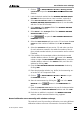
9. At the end of the measurement, a curve is printed out. This
curve should satisfy the following conditions:
• The plotted diagonal must be straight.
• At -200 mV, the current should be -1.6…-2.4 μA.
• At +200 mV, the current should be +1.6…+2.4 μA.
Perform a peak test with the dummy cell
For testing the peak measurement, the dummy cell of the 797 VA
Computrace stand is used with the test method Test797_D.mth.
Proceed as follows:
1. Click on
or MAIN WINDOW / Mode / Determination.
2. Click on
or MAIN WINDOW / Window / Working method
specification
to open the WORKING METHOD SPECIFICATIONS
window.
3. Click on
or MAIN WINDOW / File / Load method.
4. Select the method file
Test797_D.mth in the OPEN window and
click
<OK>. The method is loaded into the WORKING METHOD
SPECIFICATIONS
window.
5. Connect the dummy cell at the 797 VA Computrace stand: At-
tach electrode cable AE to clamping screw AE, attach elect-
rode cable RE to clamping screw RE, attach electrode cable WE
to clamping screw WE-D.
6. Click on
or MAIN WINDOW / Window / Monitor to open
the
MONITOR window.
7. Start the measurement by clicking the icon in the MAIN
WINDOW
or the button in the MONITORING win-
dow.