
Instruction Manual


8.6 Analyze Electroplating Bath Solutions
797 VA Computrace – Software
239
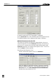
Note: To make sure that always the latest calibration file is ta-
ken for the calculation, the path of the calibration file defined
for the parameter Calibration curve on the Determination tab (of
the window EDIT WORKING METHOD PARAMETERS with cali-
bration
"DT Suppressors with calibration curve", must match
with the path defined for the parameter Data folder (for the cur-
rently logged-in user) on the tab User Directories of the window
USER RIGHTS.
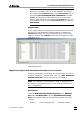
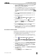
Sample table
In the Sample table, list (according to the arrangement on the sam-
ple rack) for every Suppressor standard solution a method with
Calibration technique "DT Record calibration curve" and for every
sample a method with Calibration technique "DT Suppressors with
calibration curve":
Start determination.
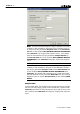
Suppressor Analysis with 838 Advanced Sample Processor and RC
Following installations and settings are recommended for the au-
tomated Suppressor determination with the 838 Advanced
Sample Processor and the "response curve technique":
Note: The "response curve technique" is used for Suppressor de-
termination in electroplating baths, if the “dilution titration techni-
que" is inapplicable.
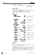
Instruments
Install the 838 Advanced Sample Processor, two 800 Dosi-
nos and a 732 Relay Box with two 823 Membrane Pump
Units (see Hardware Manual 797 and 838 Instructions for Use).
Dosinos:
Dosino 1: 50 mL Exchange Unit Electrolyte solution