
Manual


1.2 Operating principle
4 768 KF Oven
1.2 Operating principle
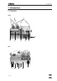
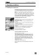
Operating scheme:
Sample temp.
Heater glass
Air filter
Measurement of
Sample boat
Air pump
Valve
To KF titration cell
Moves
Drying flasks with molecular sieves
Magnet
Setting the
gas flow
the gas flow
Interior of the oven
sample boat
"PURGE"
"TRANSFER"
Valve to
Valve to
Gas flow
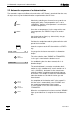
If air is used as the carrier gas, work is carried out with the air pump built into the oven.
The pump draws in the air through the air filter.
If a different gas is used as carrier gas, this is introduced via the connection "Air/N
2
in".
The gas flow is set with the valve on the side of the oven and the gas led through the
drying flasks. The gas flow is measured immediately before entry into the insert tube.
If the valve is set to "PURGE", the gas flows out again through the opening "Purge". It is
thus led through the cold, front part of the insert tube.
If the valve is set to "TRANSFER", the gas flows through the entire insert tube, i.e. also
through the hot zone of the oven. The gas exits through the outlet at the end of the insert
tube and is led to the titration cell where the moisture of the sample is determined by
titration.
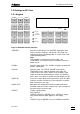
To Oven
From Oven
To Oven
Purge
Air/N2 in
Air out