
User Manual
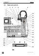
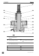

Table of contents
766 IC Sample Processor
IV
6.4 Diagnosis ....................................................................................... 117
6.4.1 General Information .............................................................117
6.4.2 Preparing the instrument .....................................................118
6.4.3 Working memory (RAM).......................................................119
6.4.4 Display..................................................................................119
6.4.5 Keyboard ..............................................................................120
6.4.6 Remote interface..................................................................121
6.4.7 RS232 interface....................................................................122
6.4.8 External Bus interface ..........................................................122
6.4.9 Beeper ..................................................................................123
6.4.10 Rack code recognition.......................................................123
6.5 Initialize data memory ................................................................. 124
6.6 Validation / GLP............................................................................ 126
6.7 Warranty and conformity............................................................ 127
6.7.1 Warranty ...............................................................................127
6.7.2 EU Declaration of conformity...............................................128
6.7.3 Certificate of conformity and system validation ..................129
6.8 Standard equipment .................................................................... 130
6.9 Optional accessories................................................................... 132
6.10 Index ............................................................................................. 133
List of figures
Fig. 1: Side view of the 766 IC Sample Processor ...................................................2
Fig. 2: Rear of the 766 IC Sample Processor ..........................................................4
Fig. 3: Setting the mains voltage.......................................................................... 11
Fig. 4: Keyboard connection ............................................................................... 12
Fig. 5: Installing the splash protection.................................................................. 13
Fig. 6: Needle installation.................................................................................... 14
Fig. 7: Sample rack placing................................................................................. 14
Fig. 8: Adjusting the sample rack ....................................................................... 15
Fig. 9: Installing the pump tubing ........................................................................17
Fig. 10: Opening chain links.................................................................................. 18
Fig. 11: Interconnection with IC system without suppression...................................20
Fig. 12: Interconnection with IC system with suppression with 766 as "Master"......... 20
Fig. 13: Interconnection with IC system with suppression with PC as "Master".......... 21
Fig. 14: Interconnection with IC system for anion/cation system .............................. 21
Fig. 15: Interconnection with IC system with dialysis............................................... 22
Fig. 16: Connection possibilities for the RS232 interface ........................................ 23
Fig. 17: Schematic representation of the instrument dialog ..................................... 47
Fig. 18: Installation of the preconcentration column ............................................... 86