
User Manual
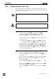

2.3 Attaching the accessories
766 IC Sample Processor
17
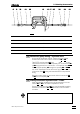
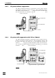
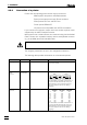
88 3535 1010 3636 1313 1515 3636 3535 18181717 343466
Fig. 9: Installing the pump tubing
66 PEEK compression fitting
(6.2744.010)
1717 Snap-action lever
88 PEEK capillary (6.1831.050) 1818 PEEK capillary (6.1831.060)
1010 Pump tubing (6.1826.040) 3434 PEEK compression fitting
(6.2744.010)
1313 Tubing cartridge (6.2755.000) 3535 Coupling (6.2744.030)
1515 Contact pressure lever 3636 Stopper (black-black)
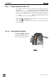
3
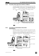
Connection pump tubing – injection valve
• At the 733 IC Separation Center, loosen the rotary nipple
screwed onto the interior side of connection 2222 or 2828.
• Take PTFE suction tubing 8484 (see Fig. 14 and Fig. 15 of the
732/733 Instructions for Use) completely out of connection 2222
or 2828 and unscrew from connection "1" of injection valve 6666.
• Pull the PEEK capillary 1818 through the opening 2222 or 2828 of
the 733 IC Separation Center and screw onto connection "1"
of injection valve 6666 using a 6.2744.010 PEEK compression
fitting.
• Retighten rotary nipple on the interior side of connection 2222
or 2828 to fix the capillary 1818.
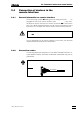
4
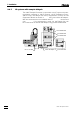
Tubing connection injection valve – waste
• Insert 6.2744.020 coupling (from 733 accessories) into con-
nection 2121 or 2727 of the 733 IC Separation Center.
• Screw PTFE suction tubing 8484 onto the 6.2744.020 coupling
attached to connection 2121 or 2727 and lead it into the waste
container.
In the case of the 733.0020 IC Separation Center with two injection
valves, it is possible to fill both sample loops from the same 766 IC
Sample Processor. For this, connection "1" of valve A (outlet of the
sample loop) must be connected to connection "2" of valve B (inlet of
the sample loop) using a 6.1803.040 PEEK capillary (15 cm).