
User Manual

2.3 Attaching the accessories
766 IC Sample Processor
15
2727
3333
3232
22
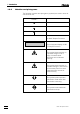
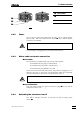
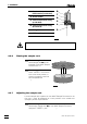
Fig. 8: Adjusting the sample rack
2
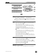
Move to adjusting position
Press <MOVE>, enter number '37' and confirm with
<ENTER>. Sample rack and swing head are turned until needle
22 is above the adjusting position 3232 (position 37: first opening of
the middle row).
3
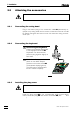
Check needle position
• Press <ê> until the needle 22 is ca. 1 cm above the upper
level of the sample rack 2727.
• Check needle position: If the needle 2 cannot be lowered
unhindered through the upper hole of the adjusting position
32, continue directly with point 4.
• Continue lowering the needle by pressing <ê> until the
needle 22 is ca. 1 cm above the lower level of the sample rack
2727.
• Check needle position: If the needle 2 cannot be lowered
unhindered through the lower hole of the adjusting position
32, continue directly with point 4.
• Lower needle completely by pressing <ê>.
• Check needle position: If the needle 22 is in the middle of the
lower hole, the sample rack must not be adjusted (continue in
this case with point 5).
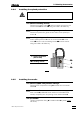
4
Adjust sample rack
• Loosen the three adjusting screws 3333 on the lower level of the
sample rack using the 6.2621.100 Allen key
• Carefully turn the two upper levels of the sample rack 2727 by
hand until the lowered needle 22 is exactly in the middle of the
lower hole at the adjusting position 3232.
• Tighten the adjusting screws 3333.
5
Move to rest position
Press <RESET> to move the sample rack to the rest position.
22 Steel neddle
(6.2624.000) or PEEK
needle (6.1835.000)
2727 Sample rack
(6.2041.430)
3232 Adjusting position 37
3333 Adjusting screw