CH-9101 Herisau/Switzerland Tel. ++41 71 353 85 85 Fax ++41 71 353 89 01 Internet www.metrohm.ch E-Mail info@metrohm.ch C 766 IC Sample Processor E R V V E 0 A 5 Y 2 O T L H N T P E I M V W M V 0 E 0 E Y 2 4 / L U S N 2 1 Q O E - I S 0 0 E N U 0 2 S S E 2 U F 1 U D Metrohm 8.766.1003 Instructions for Use 30.06.
Table of contents Table of contents 1 Introduction ....................................................................................... 1 1.1 Instrument description ................................................................... 1 1.2 Parts and controls........................................................................... 2 1.3 Information about the Instructions for Use................................ 5 1.3.1 Organization ........................................................................
Table of contents 2.4 Connection of devices to the remote interface ........................ 19 2.4.1 General information on remote interface...............................19 2.4.2 Connection cables .................................................................19 2.4.3 IC system without suppression .............................................20 2.4.4 IC system with suppression with 766 as "Master".................20 2.4.5 IC system with suppression with PC as "Master"..................21 2.4.
Table of contents 4.4.3 4.4.4 4.4.5 4.4.6 4.4.7 Setting the sample position .................................................. 71 Pump control ......................................................................... 71 Display interface signals ....................................................... 71 Interface control..................................................................... 72 Print out reports..................................................................... 73 4.5 Sample racks ........
Table of contents 6.4 Diagnosis ....................................................................................... 117 6.4.1 General Information .............................................................117 6.4.2 Preparing the instrument .....................................................118 6.4.3 Working memory (RAM).......................................................119 6.4.4 Display..................................................................................119 6.4.5 Keyboard ..........
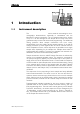
1.1 Instrument description 1 Introduction 1.1 Instrument description The 766 IC Sample Processor can be used for automating ion chromatographic determinations, especially in combination with the Metrohm IC system instruments. The 127 sample tubes with a volume of up to 11 mL are arranged on the sample rack in three rows, which guarantees easy access and unrestricted programming.
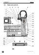
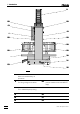
1 Introduction 1.2 Parts and controls 5 6 7 8 9 4 3 10 2 1 11 12 13 V Always install splash protection! 0 V 14 0 2 4 15 16 2 1 17 - - 11 0 0 18 2 0 19 U F U 1 D U N S I S 2 E Q S / E E E U 20 E M P M Metrohm L S E O Y N E T R 28 21 27 26 22 25 24 Always install plug cover! 23 Fig.
1.2 Parts and controls 1 Splash protection (6.2751.040) Must be installed always in operation! 15 Contact pressure lever For adjusting the contact pressure 2 Needle Steel needle (6.2624.000) or PEEK needle (6.1835.000) 16 Holding clamp For locking the tubing cartridge into place 3 Lift With swing head attached 17 Snap-action lever For releasing the tubing cartridge 4 Needle holder (attached) 18 PEEK capillary (6.1831.
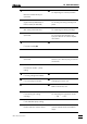
1 Introduction 9 29 29 13 19 1 29 29 28 20 20 30 Type 1.766. RS 232 31 Keyboard Made by Metrohm Herisau Switzerland 23 32 Fig. 2: Rear of the 766 IC Sample Processor 4 1 Splash protection (6.2751.040) Must be installed always in operation! 27 Sample rack (6.2041.430) 9 Guide chain For fixing tubings and cables 28 PP sample tube (6.2743.050) (can be sealed with 6.2743.060 PE caps) 13 Tubing cartridge (6.2755.000) For 6.1826.
1.3 Information about the Instructions for Use 1.3 Information about the Instructions for Use Please read through these Instructions for Use carefully before operating the 766 IC Sample Processor. The Instructions for Use contain information and warnings to which the user must pay attention in order to assure safe operation of the instrument. 1.3.1 Organization These 8.766.
1 Introduction 1.3.
1.4 Support documentation 1.4 Support documentation 1.4.1 Application Bulletins The «Application Bulletin» is a collection of analytical methods, application examples and literature references. Of Metrohm's approximately 200 Application Bulletins, 34 currently refer to ion chromatography. All these Application Bulletins are available on request free of charge from your Metrohm supplier. You will find an updated list of the Application Bulletins at any time under «http://www.metrohm.ch». 1.4.
1 Introduction • Protection against static charges Electronic components are sensitive to static charging and can be destroyed by discharges. Before you touch any of the components inside the 766 IC Sample Processor, you should earth yourself and any tools you are using by touching an earthed object (e.g. housing of the instrument or a radiator) to eliminate any static charges which exist. 1.5.
2.1 Setting up the instrument 2 Installation 2.1 Setting up the instrument 2.1.1 Packaging The 766 IC Sample Processor is supplied together with the separately packed accessories in special packagings containing shock-absorbing foam linings designed to provide excellent protection. The actual instrument is packed in an evacuated polyethylene bag to prevent the ingress of dust. Please store all these special packagings as only they can assure damage-free transport of the instrument. 2.1.
2 Installation 2.2 Mains connection Follow the instructions below for connecting to the power supply. If the instrument is operated with the mains voltage set wrongly and/or wrong mains fuse there is a danger of fire! 2.2.1 Setting the mains voltage Before switching on the 766 IC Sample Processor for the first time, check that the mains voltage set on the instrument (see Fig. 2) matches the local mains voltage.
2.2 Mains connection 220 – 240 V 100 – 120 V 220 - 240 V 100 - 120 V 220 - 240 V 26 100 - 120 V 24 Fuse holder 25 Mains connection plug 26 Mains switch 25 24 Fig. 3: Setting the mains voltage 2.2.2 Fuses One of the two fuses 0.5 A/slow-blow for 100…120 V or 0.25 A/slowblow for 220…240 V is installed in fuse holder 24 of the 766 IC Sample Processor as standard.
2 Installation 2.3 Attaching the accessories For attaching the accessories at the 766 IC Sample Processor, proceed in the order described below. 2.3.1 Connecting the swing head Plug in the branch plug of the connection cable 21 permanently attached to the swing head into the remote connection socket at the 766 IC Sample Processor and screw it onto this connection using a screwdriver (see Fig. 1). 2.3.2 Connecting the keyboard 1 Connecting the keyboard Connect the 6.2142.
2.3 Attaching the accessories 2.3.4 Installing the splash protection To avoid any danger of injury by the needle, the 6.2751.040 splash protection must always be installed when operating the 766 IC Sample Processor! 1 Remove holding screws Remove the holding screws 29 and the washer mounted on the screw threads 11 at tower 19 using the 6.2621.100 Allen key. 2 Remove protective film from splash protection Remove the plastic film glued on both sides of the splash protection 1.
2 Installation 2 Steel needle (6.2624.000) or PEEK needle (6.1835.000) 4 Needle holder 8 7 6 5 PEEK compression fitting (4.766.4030) 5 6 PEEK compression fitting (6.2744.010) 4 7 Swing head 2 8 PEEK capillary (6.1831.050) Fig. 6: Needle installation If you are using the 6.1835.000 PEEK needle, the sample tubes may not be sealed with caps because they cannot be pierced by the PEEK needle and the needle may be damaged thereby. 2.3.
2.3 Attaching the accessories 2 Steel neddle (6.2624.000) or PEEK needle (6.1835.000) 27 Sample rack (6.2041.430) 32 Adjusting position 37 33 Adjusting screw 2 32 33 27 Fig. 8: Adjusting the sample rack 766 IC Sample Processor 2 Move to adjusting position Press , enter number '37' and confirm with . Sample rack and swing head are turned until needle 2 is above the adjusting position 32 (position 37: first opening of the middle row).
2 Installation 2.3.8 Tubing connections 766 – 733 For transferring the sample from the 766 IC Sample Processor to the injection valve of the 733 IC Separation Center the following tubing connections must be made: Pump tubings are consumable material with a lifetime which depends on the contact pressure (see section 6.3.3).
2.3 Attaching the accessories 8 6 35 10 36 13 15 17 36 35 34 18 Fig. 9: Installing the pump tubing 6 PEEK compression fitting (6.2744.010) 17 Snap-action lever 8 PEEK capillary (6.1831.050) 18 PEEK capillary (6.1831.060) 10 Pump tubing (6.1826.040) 34 PEEK compression fitting (6.2744.010) 13 Tubing cartridge (6.2755.000) 35 Coupling (6.2744.
2 Installation 2.3.9 Tubing connections 766 – 754 If the 766 IC Sample Processor is used for an IC system with sample dialysis (see section 2.4.6), the peristaltic pump at the 754 Dialysis Unit is used for sample conveying instead of the pump at the 766 IC Sample Processor. The tubing connections between the 754 Dialysis Unit 754 and the 733 IC Separation Center 733 have to be made as shown in Fig. 8 of the 754 Instruction for Use.
2.4 Connection of devices to the remote interface 2.4 Connection of devices to the remote interface 2.4.1 General information on remote interface The branch plug of cable 21 leading from the swing head (see Fig. 1) is plugged into the 25 pin remote interface (see section 2.3.1). Any external devices can be connected to remote connection 22 of this branch plug. The 766 IC Sample Processor can be remote controlled via the 8 input lines, the 14 output lines can be used to control external devices.
2 Installation 2.4.3 IC system without suppression The 766 IC Sample Processor is connected to an IC system without suppression consisting of 732 IC Detector, 733 IC Separation Center and 709 IC Pump as shown in Fig. 11 using the 6.2141.110 cable. With this interconnection the standard methods 'PC', 'PC Seg', 'SP' and 'SP Seg' can be used (see section 4.6). 732 6.2125.090 cable 733 6.2125.060 cable 709 766 6.2141.110 cable Fig. 11: Interconnection with IC system without suppression 2.4.
2.4 Connection of devices to the remote interface 2.4.5 IC system with suppression with PC as "Master" The 766 IC Sample Processor is connected to an IC system with suppression consisting of 732 IC Detector, 733 IC Separation Center, 709 IC Pump and either 752 Pump Unit or 753 Suppressor Module as shown in Fig. 13 using the 6.2125.120 adaptor. With this interconnection, in which the PC is the "Master", the standard methods 'PC', 'PC Seg' and 'Preconc' can be used (see section 4.6). 732 6.2125.
2 Installation 2.4.7 IC system with sample dialysis The 766 IC Sample Processor is connected to an IC system with sample dialysis consisting of 732 IC Detector, 733 IC Separation Center, 709 IC Pump, 754 Dialysis Unit and (if suppression is used) the 753 Suppressor Module as shown in Fig. 15 using the 6.2125.120 adaptor. With this interconnection the standard method 'Dialysis' can be used (see section 4.6). If no suppression is used, the 754 Dialysis Unit can be connected to the 6.2125.
2.5 Connection of devices to the RS232 interface 2.5 Connection of devices to the RS232 interface 2.5.1 General information on RS232 interface Many different instruments may be connected via the serial RS232 interface 32. 32 In addition to all Metrohm instruments that support the Metrohm remote control language (see section 5.2) any printer with serial interface (or parallel interface and parallel/serial converter) or a personal computer (PC) may be connected.
2 Installation 2.5.2 Connection of a printer Printers with the following printer drivers may be connected: IBM IBM Proprinter and printers with IBM emulation Epson Epson printers and printers with Epson emulation Seiko Seiko printers DPU-411 and DPU-414 Citizen Citizen printer IDP562-RS HP HP printers and compatibles with HP PCL3 emulation If you connect other printers, ensure that these emulate a printer mode supported by the 766 IC Sample Processor.
2.5 Connection of devices to the RS232 interface Printer Citizen IDP562-RS Cable 6.2125.
2 Installation 26 766 IC Sample Processor
3.1 Prerequisites / Preparations 3 Operating tutorial In order to become acquainted with the 766 IC Sample Processor and its mode of operation, it is helpful to work through the short Operating Tutorial. The basic operating steps that are required to prepare the first sample series and run it with a given method are described here. For further explanations of the operation, please refer to section 4, which describes the functions of the individual keys and the programming in detail. 3.
3 Operating tutorial 3.2 Configuration CONFIG ENTER • The dialog language can be set in the configuration menu. Press configuration >auxiliaries • and then . >auxiliaries dialog: TOWER SELECT english • This menu item has a colon, indicating that here the parameters can be selected from a list. Press
3.3 Rack configuration RESET CLEAR 3.3 • At the end of this basic configuration the 766 IC Sample Processor must be turned off and on again or re-initialized by pressing to make the latest settings effective. • All data entered up to this point however, are retained. The same is true for any methods that may have been saved. Rack configuration • Using the keys <é> and <ê> you can run the lift to the desired work position for the needle.
3 Operating tutorial >rack definitions work position 2 71 mm • In any case don’t forget to confirm the value with . >rack definitions 2 rinse position 125 mm • The next menu item 'rinse position' defines the height at which the lift must be when the needle is rinsed. As for the work position, the value here can also be entered manually or automatically accepted. For the latter, the configuration menu must be exited by pressing twice and the lift newly positioned.
3.4 Methods 3.4 Methods USER METHOD • Now open the user method menu by pressing . methods >recall method • Press to load a predefined method. >recall method method: TOWER SELECT 3.5 ∗∗∗∗∗∗∗∗ • Choose 'SP' with the
3 Operating tutorial parameters >start sequence • In the submenu '>start sequence' the commands that are executed at the start of a sample series are found. >start sequence 1 CTL:Rm: < ê> INIT • The first command is a CTL command for the initialization of the remote interface. This command should be used in the start sequence of every method. Do not change anything here and press <ê>.
3.5 "Tracing" • Now move the lift into the desired position with the <ê> and <é> keys. You will notice that the current lift position is always indicated "live". During execution of the command the LEARN-LED is lit continuously. Accept the lift position that has been set by pressing and thereby exit the LEARN mode. The LEARN LED goes off again.
3 Operating tutorial >sample sequence 9 NOP < ê> • An empty line with a 'NOP'-entry (no operation) always forms the end of a sequence. • Exit the sample sequence with and go to the final sequence. • After all sample tubes have been processed, the final sequence is executed. >final sequence 1 CTL:Rm: PUMP R/S 1 • In this line the pump drive at the 709 IC Pump is switched off. Press .
4.1 Fundamentals of operation 4 Operation This section provides a detailed description of the operation of the 766 IC Sample Processor using the keyboard and dialog display. The overview of the fundamentals of operation and key functions (section 4.1) is followed by a detailed description of configuration settings (section 4.2), methods (section 4.3), manual operation (section 4.4), sample racks (section 4.5), and standard methods (section 4.6). 4.1 Fundamentals of operation 4.1.
4 Operation 4.1.2 Keyboard Metrohm SC Controller ******** counter PUMPTOWER 1 CONFIG TOWER 2 PARAM DELETE LEARN USER METHOD END HOME INSERT 1/999 ready SAMPLE MOVE LIFT 7 8 9 PUMP STIR DOS 4 5 6 TOWER RESET SCAN CTRL WAIT SELECT CLEAR 1 2 3 DEF PRINT QUIT ENTER 0 . < ENDSEQ > * LEARN HOLD STOP START 6.2142.010 Most of the keys have two functions according to whether the 766 IC Sample Processor is in the normal state or in the edit mode.
4.1 Fundamentals of operation 4.1.3 Key CONFIG PARAM USER METHOD HOME Overview of key functions Normal state Edit mode Open the configuration menu • The key opens the selection menu for the configuration of the 766 IC Sample Processor. • The settings in the configuration menu remain constant until they are changed or the working memory (RAM) for the configuration settings is re-initialized.
4 Operation Key END 38 Normal state Edit mode Lift in work position • The key runs the lift into the work position. • The work position is defined separately for every sample rack in the configuration menu under '>rack definitions' (in mm from the rest position, i.e. as measured from the upper stop). Select the last line of a menu • With the key, the last line in a menu or a sequence can be accessed.
4.1 Fundamentals of operation Key Normal state Edit mode Turn rack right • The <è> key turns the sample rack one position to the right, i.e. in the clockwise direction. The next lowest beaker position is placed under the needle. • The turning speed of the rack can be defined in the Parameter menu. • The rotation of the rack can only be carried out when the lift is at or above the shift position.
4 Operation Key RESET CLEAR Normal state Edit mode Initialization of the IC Sample Processor • The key serves to initialize the IC Sample Processor. • A method in the working memory remains unchanged. The sample rack and the lift return to their initial positions in this case. Deleting parameters, setting the default values • The key sets the initial (default) value given for a parameter.
4.1 Fundamentals of operation Key Normal state Accept data, next line • The key accepts the value entered and selects the next menu line. • A modification of data or parameters must always be confirmed by , otherwise the change will not be accepted. • If a change in a parameter is not confirmed by and another menu line is accessed, the previous value will be retained. This is indicated by an acoustic signal.
4 Operation Key LIFT 9 PUMP 4 SCAN 1 42 Normal state Edit mode Positioning the lift • Raises or lowers the lift to a predefined position. These positions (work position, rinse position, shift position, special position) can be defined in the Configuration menu as rack-specific. • An absolute lift position in mm can also be given. Numerical entry ('9') or Control pump • The key is used to switch the peristaltic pump of the 766 IC Sample Processor on or off.
4.1 Fundamentals of operation Key CTRL 2 Normal state Edit mode Interface control • Controlling of external instruments via the remote and RS232 interface. This function is used for data communication with or control of connected instruments. • The first parameter stands for the selection of the interface. The second parameter defines the state of the remote output lines or data to be transmitted via RS232 interface.
4 Operation Key Normal state Edit mode • "<" serves also for shifting the chain of characters to chose from, i.e. the text cursor is shifted one place to the left for each instance (see section 4.1.6). ENDSEQ > * Initialization • The 766 IC Sample Processor is initialized with the key followed by . • A method in the working memory remains unchanged. The rack and the lift are run to the initial position. Text entry • In a menu or sequence line in which entry of text is required, (e.g.
4.1 Fundamentals of operation Key STOP LEARN HOLD Normal state Edit mode Stop process and peripheral instruments • The key terminates a method. • Any peripheral instruments that are connected (e.g. 709 IC Pump) are not automatically stopped. In '>manual stop options', a submenu of the Parameter menu, you can specify what signal or data is to be transmitted via the interface involved (remote or RS232) during manual activation of the key.
4 Operation 4.1.4 Instrument dialog The instrument dialog of the 766 IC Sample Processor is organized in the form of so-called rolling inquiries which are arranged in menu levels in a hierarchical manner and are subject to the following rules: Main menu The main function keys , and of the 766 IC Sample Processor open a main menu whose thematically arranged submenus are selected by repeated pressing of this key or with <ê>.
4.1 Fundamentals of operation Normal state KEY Kex title >Submenu 1 QUIT ENTER >Submenu 1 Inquiry 1 ENTER KEY QUIT >Submenu 1 Inquiry 2 Key title >Submenu 2 ENTER >Submenu 1 Inquiry n ENTER >Submenu 2 Inquiry 1 ENTER KEY QUIT >Submenu 2 Inquiry 2 ENTER >Submenu 2 Inquiry n Key title >Submenu n KEY Fig.
4 Operation 4.1.5 Data entry Edit line In a menu line or a sequence one or two parameters respectively can be entered. A blinking block cursor indicates where a parameter can be entered. >changer settings lift rate 1 Û12 mm/s é ç title line ç edit line é é menu item cursor parameter >sample sequence 7 PUMP 1.1 : é é command 1st param. Û150 s ç title line ç edit line é 2nd param. The cursor keys<è> and <ç> can be used to switch between the parameters.
4.1 Fundamentals of operation 4.1.6 Text entry The text editor can be used when text entry is provided. Numbers can be entered directly via the keyboard. Opening the text editor PRINT . < ENDSEQ > * The keys "< <" or "> >" open the text editor. With "< <" an existing character string is deleted and the text cursor is set to the left margin of the edit line. With "> >" an existing character string remains and the text cursor is set on the last character of the existing text.
4 Operation Scheme >store method method: ******** "<" or ">" blinking text cursor character chain >store method Û ABCDEFGHIJ...abcd...1234...*%&/()=... method: 2x ">" blinking text cursor >store method method: Û CC DEFGHIJ...abcd...1234...*%&/()=... "<" or ">" ...... >store method method: Chloride reject accept An entire text line can be entered in this way, for example, for the naming of a method. Text editing can be ended with .
4.2 Basic settings 4.2 Basic settings 4.2.1 Configuration – key CONFIG The is used for the entry of basic settings of general applicability. If you have changed the configuration, press or switch on and off the instrument to make the entries effective.
4 Operation >auxiliaries beeper: ON ON,OFF >auxiliaries device label 8 ASCII characters >auxiliaries program 5.766.0010 read only >auxiliaries max. lift way 125 mm 0…125 mm Acoustic warning signal ON Acoustic warning signal in case of error messages OFF No warning signal Device label Freely selectable ASCII character string for characterizing the instrument (text entry, see section 4.1.6). Number of the program version Display only (no entry possibility).
4.2 Basic settings >rack definitions 2 type: M129-2 M129-2… … >rack definitions 2 work position 125 mm 0…125 mm Type description of the rack
4 Operation Settings for RS232 interface For further details on the RS232 interface, see section 5.2.
4.2 Basic settings 4.2.2 Locking keyboard functions Certain domains of the user dialog can be made inaccessible to the novice user by locking particular keys. For example, the inadvertent overwriting of a method or even the changing of parameters can be prevented in this way. Switch on + CONFIG The menu '>keyboard options' for the corresponding functions is opened by holding down the key while switching on the 766 IC Sample Processor.
4 Operation Submenu for locking method storage functions >keyboard options >user methods >user methods lock method recall: OFF Lock loading of methods ON,OFF >user methods lock method store: OFF Lock storage of methods ON,OFF >user methods lock method delete: OFF Lock deletion of methods ON,OFF >keyboard options lock display: OFF ON,OFF 56 Locking the display If the IC Sample Processor is to be operated exclusively by an external control software (e.g.
4.3 Methods 4.3 Methods 4.3.1 Structure of a method A method consists of the following parts: • Number of samples to be processed • Process sequences (start, sample and final sequence) • Definition of the various instrument settings (changer settings, manual stop options) These method parameters are accessible by pressing the key (see section 4.3.2). With the key, methods can be stored, loaded and deleted (see section 4.3.8).
4 Operation 4.3.2 Method parameters – key PARAM The key combines the most important parameter settings for the 766 IC Sample Processor. All these settings constitute a method and may be saved as such (see section 4.3.8).
4.3 Methods parameters >start sequence Start sequence of a sample series The processing sequence entered here is executed once at the start of a sample series. This can be useful for switching on external devices, for example. In this submenu up to 99 command lines can be entered as a processing sequence (see section 4.3.3). parameters >sample sequence Processing sequence for each sample This processing sequence is executed during the processing of every sample of a series.
4 Operation parameters >manual stop Actions at manual stop The following entries define the commands or signals that are transmitted via the interfaces when the key is pressed. This enables peripheral instruments connected to be stopped automatically. >manual stop CTL Rmt: ************** 14 bit (1,0 or *) Signal output via remote interface The 3 lines 11, 12 and 13 are occupied for the swing head and are therefore ignored (see section 5.1).
4.3 Methods 4.3.4 LEARN mode LEARN HOLD When editing a method, the parameters of a command are most easily determined experimentally, i.e. by manual execution, and it is for this reason that certain commands are "teachable". The LEARN function makes the manual execution of particular changer commands possible during the editing of a sequence. The resulting parameters (for example, the lift position or the status of the input lines) can be taken over in the current command line.
4 Operation 4.3.6 Commands for sequences The following commands are programmable within a sequence. Most of them are also available in manual operation but may vary partially in their operation or exhibit a limited parameter selection (see section 4.4). SAMPLE SAMPLE 7 >start sequence 1 SAMPLE: = 1 =,+,–; 1…999 Define current sample position The SAMPLE command defines the rack position for the current sample (SAMPLE = X). This is stored as a index variable.
4.3 Methods LIFT LIFT 9 >sample sequence 3 LIFT: 1 : rest mm Position the lift work,rinse,shift, special,rest,0…125 mm Raising or lowering the lift to a defined position. Work, rinse, shift and special position are rack-specifically defined in the Configuration menu under '>rack definitions' (see section 4.2.1). The rest position is the zero position (0 mm) of the lift, i.e. the upper stop. Each lift can also be precisely positioned to the millimeter.
4 Operation Predefined bit patterns are supported which can be selected by short names (e.g. 'Ready1' or 'End2'). signifies a static "ready" line of an external instrument. 'End' stands for pulse signals, for example EOD (= end of determination). When scanning for pulse signals parallel scanning of several lines cannot be applied. 'Ready' Setting special bit patterns allows flexible control of connected instruments.
4.3 Methods More detailed information about the syntax can be found in the Instructions for Use of the instrument from which the status messages should be transmitted. CTL CTRL 2 With the LEARN function transmitted data (= character strings) can be taken over interactively (see section 4.3.4).
4 Operation Data (= character string) can be sent to instruments connected via the serial RS232 interface. Make sure that the transmission parameters of the RS232 interface correspond to those of the connected instrument (see Configuration menu '>RS232 settings', section 4.2.1). Any letters, numbers and special characters can be chosen from the character set of the 766 IC Sample Processor. This function is suitable for instruments with Metrohm remote control language.
4.3 Methods 4.3.7 Process control START STOP LEARN HOLD RESET CLEAR QUIT With a method is started from the normal state. If there is no manual intervention or unexpected errors, the sample series is correctly processed and closed with the final sequence. The sample sequence is executed repeatedly according to the entry under 'number of samples', beginning with the sample tube that is defined as 'SAMPLE'.
4 Operation 4.3.8 User defined methods USER METHOD The key is used for the management of user defined methods, which can be stored and recalled under freely selectable names. A method comprises the parameters defined under the key. The key opens the following main menu: methods >recall method Recall method methods >store method Store method methods >delete method Delete method Repeated pressing of the key selects the submenus in turn.
4.3 Methods Deletion of methods methods >delete method >delete method method: ******** 8 ASCII characters >delete method delete ******** ? 4.3.9 Selection of the method Selection of the method which should be deleted using the
4 Operation 4.4 Manual operation 4.4.1 Turning the sample rack / Positioning the samples Using the <ç> and <è> keys the sample rack can be turned one position to the left (in the counterclockwise direction) or right (clockwise). MOVE manual operation MOVE 1 : 8 sample Position vessel / Turn rack sample,spec.1…8, 1…999 With the MOVE command, a particular sample tube or other vessel can be placed under the needle.
4.4 Manual operation 4.4.3 Setting the sample position SAMPLE 7 manual operation SAMPLE: = 1 Define current sample position 1…999 The command serves to set the current sample position. It defines the first sample tube for the subsequent sample series. 4.4.4 .4.4 Pump control PUMP 4 ******** counter PUMP+ 1/128 ready Switch pump on/off PUMP+,PUMP- The PUMP command is used to switch on/off the peristaltic pump at the 766 IC Sample Processor.
4 Operation 4.4.
4.4 Manual operation 4.4.7 .4.7 Print out reports PRINT . < ******** counter Print: Print out a report 1/128 param all config param usermeth All reports in the order usermeth, config, param Configuration report Method parameter report Report of stored methods The key is used for the output of reports on an external printer or PC connected to the RS232 interface (see section 2.5). Example of "config" report 'co 766 IC Sample Proc. 0100 5.766.
4 Operation Example of "param" report 'pa 766 IC Sample Proc. 0100 5.766.0010 parameters method ******** number of samples: rack >start sequence >sample sequence >final sequence >changer settings rack number 0 lift rate 1 12 mm/s shift rate 20 >manual stop CTL Rmt: ************** CTL RS232: ------------ Example of "usermeth" report 'um 766 IC Sample Proc. 0100 user memory >methods PC PC Seg SP SP Seg An Cat AnCatSeg Preconc Dialysis remaining bytes ------------ 74 5.766.
4.5 Sample racks 4.5 Sample racks 4.5.1 Standard rack (6.2041.430) Metrohm delivers the following standard sample rack for the 766 IC Sample Processor: Type M129-2 Number of vessels 127 2 Type of vessel Predef. code Predef. rack no. PP Sample tube (6.2743.050; 11 mL) PE Bottle (6.1608.080; 300 mL) 010001 2 If desired, other user-defined racks can be delivered and defined in the instrument via PC software. Irregular arrangements of vessel positions are also possible. 4.5.
4 Operation Magnets inserted In this example the code is: 000110 Rack bottom view In order to assign a certain sample rack for different applications, certain properties or recognition data can be defined for up to 16 racks. This is useful when a certain beaker size or the size of the sample series or a certain course of processing is to be predefined in an application. 4.5.
4.5 Sample racks The rack Type serves for the assignment to a position table internal to the instrument, in which the positions of the sample tubes in the rack are defined in tenths of a degree (0-3599) of the full turning angle. The rack type is coded as Mxxx-y, whereby M stands for Metrohm-defined types. The placeholder xxx stands for the number of sample tubes in a rack. The numerical code y is a special code for the number of rows on a rack (0 = single-row, 1 = double-row, 2 = triple-row).
4 Operation 4.5.4 Special beakers Special beakers are reserved positions in a sample rack. 0 to 8 special beakers can be defined per rack. They can be placed under the needle during method processing for particular operations without interrupting or hindering the sample series run. Special beakers can be used in a sample sequence for rinsing the needle. Special beakers are placed under the needle with 'MOVE 1 : spec.1'.
4.6 Standard methods 4.6 Standard methods The following pages contain the listing of standard user methods included with the instrument with explanations of the important commands. A prerequisite for the use of these methods is a correct configuration of the 766 IC Sample Processor for the 6.2041.430 sample rack supplied (M129-2).
4 Operation Settings in the «IC Metrodata» program Definition of IC method (analysis time, start parameters for IC instruments 732, 733 and 709, etc.), additional association of this method with the following time program for the 732 IC Detector: Method / Equipment / Setup / Program / Text: 0.0 Puls_766_set Set remote line 3 at 732/1 to 1 (s. below) 0.1 Puls_766_reset Set remote line 3 at 732/1 to 0 (s. below) 0.
4.6 Standard methods Settings in the «IC Metrodata» program Definition of IC method (analysis time, start parameters for IC instruments 732, 733 and 709, etc.), additional association of this method with the following time program for the 732 IC Detector: Method / Equipment / Setup / Program / Text: 0.0 Puls_766_set Set remote line 3 at 732/1 to 1 (s. below) 0.1 Puls_766_reset Set remote line 3 at 732/1 to 0 (s. below) 0.
4 Operation Settings for 732 IC Detector Setting the measurement parameters. Settings in the «IC Metrodata» program Definition of an IC method without method associated remote control. The analysis time Duration must be equal to the waiting time WAIT entered under sample sequence in the 766 IC Sample Processor. Procedure at program start 1. Create new queue in the program «IC Metrodata» and start it. 2. Enter parameter number of samples for 766 IC Sample Processor. 3.
4.6 Standard methods Settings for 732 IC Detector Setting the measurement parameters. Settings in the «IC Metrodata» program Definition of an IC method without method associated remote control. The analysis time Duration must be equal to the waiting time WAIT entered under sample sequence in the 766 IC Sample Processor. Procedure at program start 1. Create new queue in the program «IC Metrodata» and start it. 2. Enter parameter number of samples for 766 IC Sample Processor. 3.
4 Operation Settings in the «IC Metrodata» program 1. Definition of anion method for channel 1 (analysis time, start parameters for IC instruments 732, 733 and 709, etc.), additional association of this method with the following time program for the 732/1 IC Detector: Method / Equipment / Setup / Program / Text: 0.0 Puls_766_set Set remote line 3 at 732/1 to 1 (s. below) 0.1 Puls_766_reset Set remote line 3 at 732/1 to 0 (s. below) 0.
4.6 Standard methods 7 CTL:Rm: STEP MSM 753 8 PUMP 1.1 : 150 9 CTL:Rm: ZERO 1 10 CTL:Rm: INJECT A 1 11 SAMPLE: + 1 12 MOVE 1 : sample 13 PUMP 1.1 : 5 14 LIFT: 1 : work 15 CTL:Rm: ******0*010*** 16 CTL:Rm: INIT 732 17 PUMP 1.
4 Operation 4.6.7 Method "Preconc" Application Preconcentration of samples with very low concentrations in an preconcentration column (trace analysis). Interconnection see Fig. 13 Installation of the preconcentration column The preconcentration column, consisting of the 6.1006.200 Metrosep Anion preconcentration cartridge and the 6.2828.010 glass cartridge holder, is installed at the injection valve of the 733 IC Separation Center instead of the sample loop (see Fig. 18).
4.6 Standard methods >final sequence >changer settings rack number 0 lift rate 1 12 mm/s shift rate 20 >manual stop CTL Rmt: ************** CTL RS232: ------------ − —— Settings for changer functions —— − —— Reaction to manual stop ——— Settings in the «IC Metrodata» program Definition of IC method (analysis time, start parameters for IC instruments 732, 733 and 709, etc.
4 Operation >final sequence 1 CTL:Rm: PUMP R/S 1 >changer settings rack number 0 lift rate 1 12 mm/s shift rate 20 >manual stop CTL Rmt: ************** CTL RS232: ------------ − Switch off 709 IC Pump − —— Settings for changer functions —— − —— Reaction to manual stop ——— Settings for 732 IC Detector Setting of measurement parameters and creation of a program according to section 3.3.2 of the 754 Instruction for Use. For the program type, select remote instead of cycle.
5.1 Remote interface 5 Interfaces 5.1 Remote interface Peripheral instruments connected such as 732 IC Detector, 709 IC Pump, 752 Pump Unit, etc. can be controlled via the remote interface (25-pin socket). 14 lines (Output 0 – 13) are available for the emission signals. Lines 11 – 13 are used for swing head control. For receiving signals (e.g. the "ready" signal of the 732 IC Detector) 8 lines (Input 0 – 7) are provided. Line 7 is used for the swing head. 5.1.
5 Interfaces For the 766 IC Sample Processor, the output lines 11–13 and the input line 7 are occupied for the control of the swing head. These four lines are not continued in the plug and ignored, when further instruments are connected via the remote cable (see section 2.4). Various remote cables are available to use the specific functions of the individual instruments of the various Metrohm model lines (see section 2.4).
5.1 Remote interface Input lines The 8 input lines of the remote socket are queried during method processing with the "Scan" command (SCN). Method processing is interrupted until the predefined bit pattern compares to the effective state of the input lines (for example, the status of the ready line of the 732 IC Detector). An 8-place bit pattern must be set for this. Every bit is assigned to an input line. If there is correspondence, method processing will continue with the next command line.
5 Interfaces CTL commands Parameter Bit pattern Function Signal INIT 00000000000000 initializes the remote interface static INIT 732 ***0000*000**0 initializes the remote lines at 732/1 and 732/2 static PROG R/S 1 ***000*******1 starts/stops time program at 732/1 pulse (200 ms) PROG R/S 2 ******0*100*** starts/stops time program at 732/2 pulse (200 ms) PUMP R/S 1 ***001*******0 starts/stops 709/1 IC Pump pulse (200 ms) FILL A 1 ***010*******0 switches valve A at 733/1 to "Fill" pu
5.2 RS232 interface 5.2 RS232 interface 5.2.1 General rules for remote control The 766 IC Sample Processor is equipped with the comprehensive Metrohm remote control language, which allows full control over the instrument via an RS232 interface, i.e. the 766 IC Sample Processor can receive data from an external device or send data to an external device. The 766 IC Sample Processor sends 2×CR and LF as the terminator of a requested data block.
5 Interfaces 5.2.2 Call-up of objects A section from the object tree is shown below: Node 3 Language Node 2 Node 1 Prog Aux RSset Config Mode Node 0 & Root The following rules apply to the call-up of objects: Rules Examples The root of the tree is designated by ‘&’. For the call-up of an object, the nodes (levels) of the tree are marked by a point (.). For the call-up of the objects, as many characters as necessary to allow unambiguous allocation of the object suffice.
5.2 RS232 interface 5.2.3 Trigger Triggers initiate an action at the 766 IC Sample Processor, e.g. sequence start or data transmission. Triggers are marked by the introducer '$'. The following triggers are possible: $G Go Starts processes, e.g. starting the mode run or setting the RS232 interface parameters $S Stop Stops processes $Q Query Used to request all information from the current node in the tree forwards up to and including the values $Q.
5 Interfaces 5.2.4 Status messages To ensure appropriate control of an external control unit is possible, it must also be possible to request status conditions which provide information on the status of the 766 IC Sample Processor. The output of a status message is triggered by the trigger '$D'. Status messages consist of the global status, the detailed status and eventual error messages.
5.2 RS232 interface 5.2.5 Error messages Error messages ‘EXXX’ are appended to the status message and separated from this by a ‘;’. Error Meaning Exit/Corrective action E1 Incorrect program checksum Inform Metrohm service. E2 RAM read/write error Inform Metrohm service. E3 RAM lost data . If instrument adjustment is necessary, inform Metrohm service. E4 Timer interrupt for multi-tasking missing Inform Metrohm service. E5 RS232 module test error Inform Metrohm service.
5 Interfaces 5.2.6 Remote control commands The remote control tree can be divided into the following main branches: & à Mode à Config à Info à Setup à UserMeth à Assembly À Diagnose Root Method parameters Instrument configuration Instrument information Settings of operating mode User-defined methods Control of assemblies Diagnostic tests The following table lists all relevant objects of the remote control tree for the 766 IC Sample Processor.
5.2 RS232 interface Object ³ Ã.FinalSeq ³ Ã.1 ³ ³ Ã.Cmd ³ ³ ³ ³ ³ ³ ³ ³ ³ ³ ³ À.* ³ * ³ : ³ ³ ³ ³ ³ À.100 ³ Ã.Changer ³ Ã.RackNo ³ Ã.L1Rate ³ À.ShRate ³ À.ManStop Ã.RemCtl À.RSCtl Meaning Entry range/Selection Final sequence Line number of the command – – Command (see Start sequence) NOP, MOVE, LIFT, SAMPLE, PUMP, SCAN, CTRL, WAIT, ENDSEQ Parameter for command (see Start sequence) Sequence end .MOVE…, .LIFT…, .SAMPLE…, .PUMP…, .SCAN…, .CTRL…, .WAIT…, .
5 Interfaces Object ³ ³ ³ Ã.R1O 1Off ³ Ã.R2O 2Off ³ Ã.Num ³ Ã.1 ³ ³ À.Value ³ : ³ À.n ³ À.Value ³ À.RSset ³ Ã.Baud ³ Ã.DataBit Ã.StopBit Ã.Parity ³.Handsh ³ À.CharSet Meaning Entry range/Selection Offset in 1/10-ang. degrees for positions in row 1 Offset in 1/10-ang. degrees for positions in row 2 Number of positions (n) Position 1 Position in 1/10-angular degrees 0…3599 0…3599 1…200 – 0…3599 Position n Position in 1/10-angular degrees – 0…3599 RS232 interface $G effects all the RS settings.
5.2 RS232 interface Object ³ Ã.Outputs ³ À.Status ³ ³ ³ ³ ³ Ã.Display ³ Ã.L1 ³ À.L2 ³ À.Counter Ã.Sample À.Maximum Meaning Entry range/Selection Remote outputs Status of the 14 output lines (Output 0…13; 1 = on, read only low, active; 0 = off, high, inactive) in byte form 13 Status = ∑2 n n=0 Display Display in LCD line 1 Display in LCD line 2 – read only read only Sample counter Current sample position Number of samples to be worked off – read only read only &Setup &Setup ³ Ã.
5 Interfaces Object ³ ³ ³ Ã.UserMeth ³ ³ Ã.Recall ³ ³ Ã.Store ³ ³ À.Delete ³ À.Display ³ Ã.AutoInfo ³ ³ ³ ³ ³ Ã.Status ³ Ã.P ³ Ã.Ch ³ ³ Ã.G ³ ³ Ã.R ³ ³ Ã.S ³ ³ Ã.H ³ ³ Ã.C ³ ³ Ã.B ³ ³ Ã.F ³ ³ Ã.OM ³ ³ À.CM ³ À.Error ³ Ã.PowerOn ³ Ã.Initialize ³ À.Select ³ ³ Ã.RamInit ³ ³ ³ À.InstrNo À.
5.2 RS232 interface Object Meaning Entry range/Selection &Assembly &Assembly ³ Ã.Sample ³ Ã.Func ³ À.Value ³ Ã.Move ³ Ã.Target ³ À.Position ³ ³ Ã.Lift ³ Ã.Station ³ À.Way ³ ³ Ã.Pump ³ Ã.Address ³ À.Value ³ Ã.Scan ³ Ã.Address ³ À.Pattern ³ ³ ³ ³ ³ ³ Ã.Ctrl ³ Ã.Address ³ À.Pattern ³ ³ ³ ³ ³ ³ ³ ³ Ã.Wait ³ À.Time ³ À.
5 Interfaces Object Meaning Entry range/Selection &Diagnose &Diagnose ³ Ã.Init ³ À.Select ³ ³ Ã.RamTest ³ Ã.LcdTest ³ Ã.ContrastTest ³ Ã.KeyTest ³ Ã.IoTest ³ Ã.RsTest ³ Ã.EbusTest ³ Ã.BeeperTest ³ Ã.RackcodeTest ³ Ã.FunctionTest ³ Ã.SimulateKey ³ ³ ³ ³ ³ ³ ³ ³ ³ ³ ³ ³ ³ ³ ³ ³ ³ ³ ³ Ã.InstrNo ³ ³ À.PowerOn 104 Diagnosis (see section 6.
5.2 RS232 interface 5.2.7 Data transmission protocol The RS232 interface of the 766 IC Sample Processor is configured as DTE (Data Terminal Equipment) with the following technical specifications: • Standard Data interface in accordance with EIA standard RS 232C (DIN 66020, page 1), transmission parameters can be set under 'configuration/RS232 settings', see section 4.2.1. • Control characters CR LF XON XOFF • Max.
5 Interfaces 5.2.8 Handshake No Handshake (none) The 766 IC Sample Processor neither checks handshake inputs (CTS, DSR, DCD) nor sets handshake outputs (DTR, RTS). Reduced hardware handshake (HWs) 766 IC Sample Processor as receiver: 766 External device DTR DTR LF RxD RxD Time 766 IC Sample Processor as sender: 766 External device RTS RTS CTS CTS LF TxD TxD Time The data flow can be interrupted by deactivating the CTS line.
5.2 RS232 interface 766 IC Sample Processor as sender: 766 External device RTS RTS DSR DSR DCD DCD CTS CTS LF TxD TxD Time The data flow can be interrupted by deactivation of the CTS line. Software handshake with character stop (SWchar) Handshake inputs are (CTS, DSR, DCD) are not checked at the 766 IC Sample Processor, handshake outputs (DTR, RTS) are set. As soon as an LF is recognized, the 766 IC Sample Processor sends XOFF.
5 Interfaces 766 IC Sample Processor as sender: 766 External device XOFF XON Data output RxD LF TxD max. 4 char. Data output disabled Data input Data output enabled Time Software handshake with line stop (SWline) Handshake inputs are (CTS, DSR, DCD) are not checked at the 766 IC Sample Processor, handshake outputs (DTR, RTS) are set. The 766 IC Sample Processor has an input buffer which can accept a string of up to 80 characters + CR LF.
5.2 RS232 interface 5.2.9 Pin assignment RS232C interface external Transmitted Data (TxD) If no data transmission takes place, the line is maintained in the ”ON” condition. Data are sent only when CTS and DSR are in the ”ON” condition and DCD is in the ”OFF” condition. Pin 2 Received Data (RxD) Data are received only when DCD is ”ON”. Pin 3 Transmitted Data Received Data Request to Send (RTS) ON condition: 766 IC Sample Processor is ready to send data.
5 Interfaces 5.2.10 RS232 error rectification Problem Questions for corrective action No characters can be received on an attached printer. ⇒ Are the devices switched on and the connecting cables plugged in properly? ⇒ Is the printer set to ”on-line”? ⇒ Do the baud rate, data bits and parity for the two devices have the same setting? ⇒ Is the handshake set properly? If everything appears ok, try to print out a report by pressing the key.
6.1 Error messages 6 Appendix 6.1 Error messages When an error occurs the execution of the active command is interrupted and an error message is displayed (display blinks). This must be acknowledged with the key. If an error occurs during processing of a sample series, the 766 IC Sample Processor will then be switched into the "HOLD" state. After the cause of the error has been rectified, the sample series can be continued with the next command in the active sequence by pressing the key.
6 Appendix 112 Error message Cause * changer low power The power supply cannot deliver enough power for the simultaneous operation of all components currently in use (pump, lift). * RS232 error The transmission parameters of the RS232 interface do not agree with those of the receiving instrument. * check rack/swing head Invalid configuration of sample rack or swing head. * invalid position The sample position selected is defined as a special beaker or the special beaker chosen is not defined.
6.2 Technical data 6.2 Technical data Lift Lift path ca. 125 mm Load ca. 30 N Stroke speed adjustable, 3…12 mm/s Turntable Turning speed adjustable, 3…20 angular degrees/s Pump Pump type 1-channel peristaltic pump with rotational speed of 20 /min (50 Hz) 24 /min (60 Hz) Pump capacity (with water, without counterpressure) with 6.1826.040 pump tubing: typ. 0.9…1.1 mL/min (depends on contact pressure) Pressure max. 1.5 bar (0.
6 Appendix Safety specifications Construction / Testing According to IEC 1010 / EN 61010 / UL 3101-1, protection class 1, degree of protection IP40 Safety directions The Instructions for Use include information and warnings which must be heeded by the user to assure safe operation of the instrument. Electromagnetic compatibility (EMC) Emitted interference Standards met: EN55011 (class B), EN55022 (class B), EN50081-1 01.
6.3 Maintenance and servicing 6.3 Maintenance and servicing 6.3.1 Maintenance by Metrohm service Maintenance of the 766 IC Sample Processor is best done as part of an annual service performed by specialists from the Metrohm company. If work is frequently performed with caustic and corrosive chemicals, it may be necessary to shorten the interval between servicing. The Metrohm service department is always willing to offer expert advice on the maintenance and servicing of all Metrohm instruments. 6.3.
6 Appendix 6.3.3 Replacing the pump tubing Pump tubings are consumable material with a limited lifetime and should be replaced at regular intervals (approx. every 2 weeks under continuous use). The working life of pump tubing depends to a considerable extent on the contact pressure. This is why the contact pressure must be correctly set as described in section 2.3.8.
6.4 Diagnosis 6.4 Diagnosis 6.4.1 General Information The 766 IC Sample Processor is a very precise and reliable control instrument. Thanks to its rugged construction, its functions are rarely influenced by mechanical or electrical affects. Although an occasional fault in the instrument can not be excluded completely, it is certainly much more likely that malfunctions are caused by wrong operation or handling or by improper connections and operation with non-Metrohm instruments.
6 Appendix Required Instruments: Only required, if the RS232 or remote interface is to be checked: • 3.496.8550 Test plug (on the "Remote" plug) • 3.496.8480 Test plug (on the "RS 232" plug) 6.4.2 Preparing the instrument • Disconnect power plug. • Remove cables to the "RS232" and "Remote" interfaces. • Plug in power plug and immediately press <9> and keep it depressed until the start test pattern disappears. • Alternatively, the key can be pressed to cause a reset followed by pressing (within 0.
6.4 Diagnosis 6.4.3 Working memory (RAM) This diagnosis step completes a non-destructive test over the entire range of the RAM contents (working memory). • Prepare instrument for diagnosis (see section 6.4.2). • If necessary, press <ê> several times until diagnosis >RAM test • If no errors are found, this appears on the display: >RAM test RAM test ok • diagnosis >display test 6.4.4 Display With this diagnosis step, the functionality of the LED’s and the display is tested.
6 Appendix • The test can be exited with the or keys. diagnosis >display contrast test • After pressing the key the following display appears whereby the contrast of the display continuously varies between bright and dark. >display contrast test 766 IC Sample Processor • The test can be exited with the or key. diagnosis >key test 6.4.5 Keyboard This diagnosis step allows all the keys on the keyboard to be tested for their functionality.
6.4 Diagnosis Key code table Code Key 0 Key 16 <7 / SAMPLE> 1 17 <4 / PUMP> 2 18 <1 / SCAN> 3 19 <0> 4 20 5 21 <è> 6 22 23 7 6.4.6 Code 8 <9 / LIFT> 24 <é> 9 <6> 25 < ê> 10 <3 / WAIT> 26
6 Appendix 6.4.7 RS232 interface This diagnosis step tests the functionality of the serial interface. • Prepare instrument for diagnosis (see section 6.4.2). • If necessary, press <ê> several times until diagnosis >RS232 test • >RS232 test RS232 test connector ? • Insert the 3.496.8480 test plug into the RS232 interface without turning off the instrument. • The test runs automatically.
6.4 Diagnosis 6.4.9 Beeper • Prepare instrument for diagnosis (see section 6.4.2). • If necessary, press <ê> several times until diagnosis >beeper test • The beeper is turned on and off in an endless loop. >beeper test • The test can be exited by pressing the or keys. diagnosis >rack code test 6.4.10 Rack code recognition This diagnosis step checks the functionality of the sensors with regard to their ability to automatically recognize the attached rack.
6 Appendix • The test reads the code continuously and displays it immediately. For representation on the screen a 6-place bit pattern is provided (code ??????). The first position is for magnet no. 1, the second position for magnet no. 2, etc. If a magnet is recognized, a “1” is written into the corresponding position, otherwise a “0” is assigned. • Position all racks which are used one after the other and compare the notes made before the test with the information on the display.
6.5 Initialize data memory • Prepare instrument for diagnostic test (see section 6.4.2). • If need be, press <9> key repeatedly until diagnosis >RAM initialization • Press key to open the following diagnostic menu: >RAM initialization select: param ü >RAM initialization select: config ü >RAM initialization select: setup ü >RAM initialization select: assembly >RAM initialization select: ü ü all Set method parameters with default values.
6 Appendix 6.6 Validation / GLP GLP (Good Laboratory Practice) requirements include the periodic check of analytical instruments for reproducibility and accuracy using Standard Operating Procedures (SOP). Although the instrument in question is not a measuring instrument, it is recommended to include the 766 IC Sample Processor in the validation of an analytical system as a part of it.
6.7 Warranty and conformity 6.7 Warranty and conformity 6.7.1 Warranty The warranty on our products is limited to defects that are traceable to material, construction or manufacturing error which occur within 12 months from the day of delivery. In this case, the defects will be rectified in our workshops free of charge. Transport costs are to be paid by the customer. For day and night operation, the warranty is limited to 6 months.
6 Appendix 6.7.2 EU Declaration of conformity EU Declaration of Conformity The METROHM AG company, Herisau, Switzerland hereby certifies that the instrument: 766 IC Sample Processor meets the requirements of EC Directives 89/336/EWG and 73/23/EWG.
6.7 Warranty and conformity 6.7.3 Certificate of conformity and system validation Certificate of Conformity and System Validation This is to certify the conformity to the standard specifications for electrical appliances and accessories, as well as to the standard specifications for security and to system validation issued by the manufacturing company. Name of commodity: 766 IC Sample Processor Name of manufacturer: Metrohm Ltd.
6 Appendix 6.8 Standard equipment Subject to changes ! All dimensions are given in mm. The 2.766.0010 IC Sample Processor includes the following parts: Quant. Order No. Description 2 6.1608.080 PE Bottle 300 mL Bottle for special beaker positions 1 (128) and 2 (129) 128 67 2 1 2 1 6.1826.040 6.1831.050 6.1831.060 6.1835.000 150 Pump tubing made of PVC (Tygon); with 2 firmly attached black-black stoppers; i.d. = 0.76 mm, e.d. = 2.27 mm 400 PEEK Capillary Length = 40 cm 0.5 1.
6.8 Standard equipment Quant. Order No. Description 1 6.2142.010 Keyboard for 766 IC Sample Processor 1 6.2621.060 Open-end spanner 5⁄16" 94 2 6.2621.090 Open-end spanner 1⁄2" 147 1 1 6.2621.100 6.2624.000 Allen key 3 mm For Allen screws on sample rack and for splash protection 63 SW3 20 1.5 Steel needle For aspiration of solutions from sealed sample tubes 150 1 6.2743.050 PP Sample tube (11 mL) For 6.2041.430 sample rack; set of 2000 2 6.2743.060 PE Cap For sealing the 6.2743.
6 Appendix 6.9 Quant. Order No. Description 1 8.766.1003 Instructions for Use (English) for 766 IC Sample Processor 1 8.766.1013 Quick Reference Guide (English) for 766 IC Sample Processor Optional accessories Order No. Description 6.1831.040 PEEK Capillary Length = 15 cm For the connection of two injection valves at the 733 IC Separation Center 1.59 0.5 6.2125.090 Connection cable Connection cable 766 IC Sample Processor – 6.2125.120 Adaptor 6.2125.
6.10 Index 6.10 Index A Actions at manual stop......................................... 60 Adaptor (6.2125.120) Interconnection..................................... 20,21,22 Ordering designation.................................... 132 Remote control............................................... 91 Adjusting position 32 Adjusting the sample rack.............................. 15 Figure ............................................................. 15 Adjusting screw 33 Adjusting the sample rack............
6 Appendix F K Filling two sample loops ...................................... 17 Final sequence........................................... 34,57,59 Fundamentals of operation.................................. 35 Fuse holder 24 Cahnge fuses ................................................. 11 Figure .......................................................... 3,11 Setting mains voltage..................................... 10 Fuses .......................................................
6.10 Index Method parameters.............................................. 58 Method processing .............................................. 35 Methods Commands for sequences ............................ 62 Delete ............................................................. 69 Hold ................................................................ 67 Locking functions ........................................... 56 Method name ................................................. 68 Method parameters...........
6 Appendix Pump drive 14 Figure ............................................................... 3 Pump status ......................................................... 35 Pump time............................................................ 63 Pump tubing 10 Connection to needle ..................................... 16 Figure .......................................................... 3,17 Installation ...................................................... 16 Life time........................................
6.10 Index Special position............................................... 30,77 special position.......................................... 53 Splash protection 1 Figure ....................................................... 3,4,13 Installation....................................................... 13 Ordering designation.................................... 131 Remove protection film .................................. 13 Safety rule.........................................................
6 Appendix 138 Keys Menus < < > .............................................................. 49 < > > .............................................................. 49 .................................................. 40,46,67 .......................................... 28,37,51,55 ............................................... 43,65,72,92 ..................................................... 39,60 <ê>..........................................................