
Owner's manual
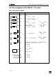
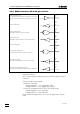
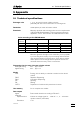
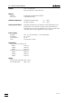
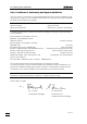
Table Of Contents
- Content
- Overview
- Operation with the keyboard
- Error messages, troubleshooting
- Diagnosis
- General
- Summary
- Prepare instruments for diagnostic tests
- Diagnosis of cylinder code
- Diagnosis of key board
- Diagnosis of display
- Diagnosis analog output
- Diagnosis of digital timer
- Diagnosis of analog timer
- Diagnosis of external inputs, outputs
- RAM-test
- Diagnosis of spindle zero and cock changeover
- Diagnosis of spindle drive
- RAM-initialisation
- Releasing a locked spindle
- Operation via RS232 Interface
- Appendix
- Index
4.4 Pin assignment of the RS232 / I/O socket
765 Dosimat
49
Definition of signal states
- Data interchange circuits (TxD, RxD)
voltage negative (<-3 V): marking condition
voltage positive (>+3 V): spacing condition
- Timing and control interchange circuits (CTS, RTS, DTR, DSR,
RLSD)
voltage negative (<-3 V): OFF condition
voltage positive (>+3 V): ON condition
In the transitional range from +3 V to -3 V the signal state is unde-
fined.
Driver 1488 according to EIA RS 232C specification
Receiver 1489A according to EIA RS 232C specification
Ordering numbers for 25 pin plug (socket A):
K.210.9004 (shell) and K.210.002
Important: The pin numbers are not used according to the RS232
standard version. Therefore do not plug in standard RS232 cables!
Ordering number for 8 pin plug (socket B):
K.101.0004
No liability whatsoever will be accepted for damage caused by im-
proper interconnection of instruments.