
Owner's manual
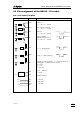
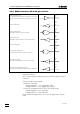
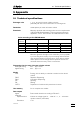
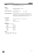
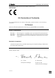
Table Of Contents
- Content
- Overview
- Operation with the keyboard
- Error messages, troubleshooting
- Diagnosis
- General
- Summary
- Prepare instruments for diagnostic tests
- Diagnosis of cylinder code
- Diagnosis of key board
- Diagnosis of display
- Diagnosis analog output
- Diagnosis of digital timer
- Diagnosis of analog timer
- Diagnosis of external inputs, outputs
- RAM-test
- Diagnosis of spindle zero and cock changeover
- Diagnosis of spindle drive
- RAM-initialisation
- Releasing a locked spindle
- Operation via RS232 Interface
- Appendix
- Index
4.4. Pin assignment of the RS232 / I/O socket
765 Dosimat
48
4.4.2 RS232 interface, 25 and 8 pin sockets
Transmitted Data (TxD).
If no data are transmitted, the line is held in the “ON” condi-
tion. Data will only be sent when CTS is in the ”ON” condi-
tion.
Received Data (RxD)
Request to Send (RTS)
ON condition: Titrino is ready to send data.
Clear to Send (CTS)
ON condition: Remote station is ready to receive data.
Signal ground (GND)
Data Terminal Ready (DTR)
ON condition: Instrument is ready to receive data.
Data Set Ready (DSR)
ON condition: Communication channel is connected.
Received Line Signal Detector (RLSD)
ON condition: The connected device is ready to send data.
Protective earthing
Direct connection from cable plug to the protective ground of the in-
strument.
Polarity allocation of the signals
- Data lines (TxD, RxD)
voltage negative (<-3 V): signal state ”ON”
voltage positive (>+3 V): signal state ”ZERO”
- Control or message lines (CTS, RTS, DTR, DSR, RLSD)
voltage negative (<-3 V): OFF state
voltage positive (>+3 V): ON state
In the transitional range from +3 V to -3 V the signal state is unde-
fined.
A19
and
B4
A4/5
and
B1
A23
and
B5
A14
and
B8
A25
and
B7
A24
and
B2
A1
and
B3
A22
and
B6