CH-9101 Herisau/Switzerland Tel. +41 71 353 85 85 Fax +41 71 353 89 01 E-Mail sales@metrohm.ch Internet http://www.metrohm.ch 765 Dosimat Instructions for Use 8.765.1023 2005.
Content Content 1 Overview ...................................................................................................................2 2 Operation with the keyboard ...................................................................................4 2.1 Keypad........................................................................................................................ 4 2.1.1 Key ......................................................................................................
Overview Explanation of symbols: < > DOS.....0.000 ml 765 Dosimat means "key", e.g.
Overview 1 Overview Front view of instrument: 1 Exchange unit Normally the models with automatic cock changeover. Note: Choose the volume of the exchange unit in such a way that a volume between 10...100% of the nominal volume is expelled. 2 Display The 16 digit display shows all important information: DOS 3.456 ml Mode (DOS = dosing) and dosed volume. Dosimat is in stand-by position DOS ↑ 3.456 ml The piston is moving upwards. DOS ↓ 3.456 ml The piston is moving downwards. DOS → 3.
Overview Rear view of instrument: 6 Data inputs and outputs Via data transfer interface according to RS 232 C including optional analogue output. For 25-pin D subminiature plug. Important: Note plug positions, page 47! Plug cables in and out only if the instruments are switched off. 7 Data inputs and outputs Via data transfer interface according to RS 232 C. For 8-pin plug. (For details see page 47) Plug cables in and out only if the instruments are switched off.
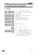
2.1. Keypad 2 Operation with the keyboard 2.1 Keypad RATE VOLUME EXP BLANK FACTOR SMPL 7 8 9 UNIT STORE RECALL 4 5 6 1 2 3 MODE 0 . – ENTER FILL CLEAR GO 6.2149.000 RATE Expelling and filling rate in all modes. VOLUME Different volumes depending on selected mode. EXP Exponent. BLANK FACTOR Calculation parameters in mode DOS. SMPL UNIT Unit in modes DOS and CNT STORE Management of user memory: RECALL Storing, loading of modes. MODE Selection of mode.
2.1 Keypad Rules for data input: • On entering a negative number, key in minus sign first; <-> is not a "change of sign" key! • Changeover between first functions (blank, factor etc.) and digits is done automatically. • Terminate parameter entries with . • Some keys are organized as inquiry drums, i.e. pressing these keys several times, display shows new inquiries. A new value is stored or a new feature is selected with . The program then returns to the initial state, the inquiry drum is left.
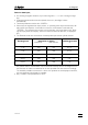
2.2. Modes 2.1.1 Key The inquiries of this key are identical for all modes. Expelling and filling rate This key is accessible live (except in mode DOS), i.e. rate can be changed during a running function . RATE ↑ ml/min Expelling rate Range for digital setting depending on volume of exchange unit: 1 mL 0.001 3.00 mL/min 5 mL 0.005 15.0 mL/min 10 mL 0.010 30.0 mL/min 20 mL 0.020 60.0 mL/min 50 mL 0.050 150.0 mL/min Key sets "OFF", i.e..
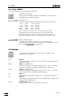
2.2 Modes Example: Selection of mode "DIS C", cumulative dispensing. Press . Display shows that mode which has been selected last with key , e.g. DOS . Press repeatedly until display shows . DIS C Load mode "DIS C" into working memory with . Display shows DIS C 0.000 ml. Mode "DIS C" is ready to work, the piston is in zero position.
2.2. Modes Calculation values BLANK 7 Blank value Input range: 0...±999.999 mL b = 0. ml f = 1. Factor Input range: 0... ±1E33 s = 1. Sample size Input range: 0...
2.2 Modes 2.2.2 Mode DIS R, Repetitive Dispensing Dosimat is dosing a stored dispensing volume if is pressed. The burette cylinder is refilled and display reset to 0.000 mL. VOLUME V-DIS 1. ml Dispensing volume Input range: 0.001...999.999 mL Expelling and filling rate, see page 6. RATE 2.2.3 Mode DIS C, Cumulative Dispensing Dosimat is dosing a stored dispensing volume if is pressed, and the dispensed volume (V–DIS) remains displayed. VOLUME RATE V-DIS 0.
2.2. Modes 2.2.4 Mode PIP, Pipetting Aspirating and subsequent expelling of a stored pipetting volume. VOLUME V-PIP 0.1 ml Pipetting volume Input range depends on the volume of the exchange unit: 1 mL 0.001... 0.900 mL 5 mL 0.001... 4.900 mL 10 mL 0.001... 9.800 mL 20 mL 0.002... 19.700 mL 50 mL 0.005... 49.
2.2 Modes • A new air bubble is built with every preparation step ("prep.") e.g. its volume increases. If you wish to keep the volume of the air bubble expel it in mode DOS before changing V-PIP. • For best pipetting results we recommend exchange units with volumes ≤ 20 mL and pipetting equipment 6.5611.000. • The aspirating and expelling rates should not be higher than 20 mL/min. • Hold tubing tip in an angle of app. 45° to the vessel wall during pipetting.
2.2. Modes Sequence of DIL DIL * DIL 0.000 ml ↓ ↓ DIL 1 ↓ prep. 0.100 ml ↓ ↓ DIL 2 DIL 1.100 ml ↓ ↓ ↓ Standard mode DIL. Preparation step: Hold burette tip free at working height. Ready to aspirate the pipetting volume: Immerse burette tip. Ready to expel the pipetting and diluting volume: Hold burette tip for pipetting. prep. Notes • If you wish to change V-PIP, it is best to change it during filling in the preparation step, i.e. when display shows DIL ↓ prep..
2.2 Modes Content entries which can be implemented in the CNT D mode are summarized below and designated with a bold frame Concentration Reference quantity (denominator) Fraction Molality Volume Sum Mass of the solution of the components j of the solvent Specified quantity mk / kg V/L (numerator) Amount of substance ni / mol Mass mi / kg Amount of substance concentration c ci = ni/V Units: mol/L, mmol/L Example: c(NaOH)=0.
2.2.
2.2 Modes The following table shows factors for the most common ionic standards: Cation Standard prepared from: Factor f Anion Standard prepared from: Factor f Na+ NaCl 0.39339 F- NaF 0.45245 NaNO3 0.27050 KCl 0.52441 Cl- NaCl 0.60666 KNO3 0.38670 KCl 0.47550 CaCl2 0.36111 NaBr·2H2O 0.57514 KBr 0.67141 I- KI 0.76444 SO42- K2SO4 0.55087 NO3- NaNO3 0.72950 KNO3 0.61319 Na2HPO4·12H2O 0.26519 Na3PO4·12H2O 0.24985 K+ Ca2+ Ba2+ Cu2+ Pb2+ BaCl2·2H2O 0.
2.2. Modes Since the volume of the solvent V0 is dispensed in the operational method of the CNT D mode, higher concentrations require a correction factor which takes the difference between V0 and V (volume of the solution) into consideration: V0 f = —– V This factor can be determined with the Dosimat in the DOS mode: A solution of the desired concentration is prepared in the conventional manner in a volumetric flask by dispensing the solvent with the aid of the Dosimat up to the mark of the flask (V0).
2.3 User memory 2.3 User memory Up to 10 modes, complete with their user selected specific parameters, can be stored in the user memory.
2.4. Special settings 2.4 Special settings Special settings can be executed by pressing keys <0> and <—> simultaneously. The display shows Sys. Soft-Reset . Press key <0> and keep it pressed until special key 0..6 appears in the display. Press key 1...6. Pressing key once, leads back to the blinking display special key 0..6 and pressing key again leads to the corresponding mode in the working memory. Pressing key , the next inquiry is displayed, with the setting is stored.
3.1 Special messages and error messages 3 Error messages, troubleshooting blinking value The value keyed in is out of the input range. 3.1 Special messages and error messages cylinder empty! The Dosimat is set to "auto fill off" and one burette volume has been expelled in mode DOS. Exit: error 1 Check sum error in PROM. Remedy: Call Metrohm-Service error 2 RAM-check: Error in on-chip-RAM. Remedy: Call Metrohm-Service error 3 RAM-check: Error in off-chip-RAM.
3.1. Special messages and error messages 20 volume .
3.2 Diagnosis 3.2 Diagnosis 3.2.1 General The 765 Dosimat is a very precise and dependable feeding instrument. Thanks to its rugged construction, it is highly unlikely that external mechanical or electrical influences will have any adverse effect on its functions. Although a fault in the instrument can not be excluded with certainty, the possibility is greater that malfunctions are caused by wrong operation or handling, through improper connections and the operation with third-party devices.
3.2. Diagnosis 3.2.2 Summary 3.2.4 Diagnosis of cylinder code ..............................................23 3.2.5 Diagnosis of key board....................................................23 3.2.6 Diagnosis of display ........................................................23 3.2.7 Diagnosis analog output .................................................24 3.2.8 Diagnosis of digital timer .................................................25 3.2.9 Diagnosis of analog timer......................
3.2 Diagnosis 3.2.4 Diagnosis of cylinder code 1. Prepare instrument for diagnostic test (see chap. 3.2.3). 2. <0> cylinder code 3. no exch. unit! 4. Insert (dummy) exchange unit. code: xx ml 5. Check whether the displayed ml-Code (xx ml) corresponds to the exchange unit. Various exchange units can be inserted to verify their ml-code. If an exchange unit is coded incorrectly or if the code switches are inoperative, the display shows: E 90: .. no code! 6. diagn. Key 0...9 3.2.
3.2. Diagnosis 2. <2> display test 3. Characters are generated for an optical check of the display: . 1. The display is written to from left to right with the character 2. Repeatedly the display is written to with the characters 3. In quick succession the display is written to with the capital letters from the alphabet. 4. The display is written to with the character set (see Fig. 1) as continuous moving display. and . The test sequence can be held by pressing key <5> and restarted.
3.2 Diagnosis 1. Prepare instrument for diagnostic test (see chap. 3.2.3). 2. Connect voltmeter, DVM or recorder by means of cable 3.980.3170 to location A (do not switch off the unit). Plug A Pin 21 (0...+1 V) Plug A Pin 11 (ground) 3. <3> analog output 4. V-out = 0.000 V Measuring instrument reads 0 V (tolerance ±6 mV). Take also into account the tolerance of the measuring instrument! 5. V-out = 1.000 V Measuring instrument reads +1.000 V (tolerance ±6 mV + tolerance of point 4.) 6.
3.2. Diagnosis 1. Prepare instrument for diagnostic test (see chap. 3.2.3). 2. <4> timer dig. test 3. timer dig. The frequency of the digital timer is measured during 1.5 s. If no fault is found, the following appears: timer dig. o.k. 4. diagn. key 0...9 3.2.9 Diagnosis of analog timer The analog timer is that part of the electronic circuit in the dosimat which is responsable for the analog spindle speed rate (adjustable with knob 'dV/dt'). 1.
3.2 Diagnosis 5. diagn. key 0...9 6. Remove test plug 3.496.8360. 3.2.11 RAM-test 1. Prepare instrument for diagnostic test (see chap. 3.2.3). 2. <8> RAM test 3. The test runs automatically. If no fault is found, the following appears: RAM TEST passed 4. diagn. key 0...9 3.2.12 Diagnosis of spindle zero and cock changeover 1. Power off. 2. Insert exchange unit. 3. Power on. Dosimat fills. 4. Remove exchange unit. 5. To check the spindle zero. The spindle must be 0.2 - 0.
3.2. Diagnosis 3. Power off and wait for 5 s. 4. Power on and simultaneously press key <0> and keep pressed until: special key 0..6 5. <3> auto fill ??? └─┬─┘ check whether display reads 'on' or 'off' (make note!) 6. Press if auto fill 'on' otherwise go on with item 7. auto fill off 7. , The dotted pattern is displayed, afterwards the display changes to the mode used last before starting the diagnosis. Dosimat fills. 8. Actuate several times until the display shows: DOS 9.
3.2 Diagnosis The spindle moves 80 mm with respect to spindle zero. Instead of the spindle height one can also measure the expelled volume (corresponding to the max. volume of the exchange unit). 17. Actuate and simultaneously take the time until the dosimat is in 'ready' position again. Filling time: one cock cycle 1s filling 18 ...
3.3. RAM-initialisation 3.3 RAM-initialisation In rare cases, it is possible that major interference signals such as line spikes and lightning can have an adverse influence on the contents of the data memory. If the contents of the data memory are undefined, this is indicated after “power on“ with ‘error 5'. The keyboard is then blocked, no entering is possible until the RAM is initialised again. 1. Disconnect all cables at rear, except mains cable. 2. Power off and wait 5 s. 3.
3.4 Releasing a locked spindle 3.4 Releasing a locked spindle with inserted Exchange Unit The burette drive may very occasionally jam at the top or bottom end of the cylinder. If jamming occurs at the top or when the drive is out of function, the Exchange Unit can no longer removed. In this case, it is necessary to proceed as follows: 2 screws (M4 countersunk) 2 screws (M3 fillister head) knob edge of bench Fig. 4 1. Disconnect instrument from power supply! 2. Remove control knob. 3.
4.1 General 4 Operation via RS232 Interface 4.1 General The Dosimat offers an extensive remote control. Data transmission occurs via an interface according to RS 232 C in half duplex procedure. The syntax of the commands is based on the following principles: • Commands are strings which always begin with a letter. • Only the first three letters are significant, string length is unlimited. • Actual parameters have to be separated by a space from the preceding command.
4.2. Control commands 4.2 Control commands 34 Command Explanation Live Notes REMOTE ON Remote control on Y 4.2.1 REMOTE OFF Remote control off Y 4.2.2 G GO N 1-byte command 4.2.3 S STOP Y 1-byte command 4.2.4 F FILL Y 1-byte command 4.2.5 C CLEAR volume display N 1-byte command 4.2.6 I Information Y 1-byte command 4.2.7 DOS Standard mode DOS N 4.2.8 DIR Standard mode DIS R N 4.2.9 DIC Standard mode DIS C N 4.2.10 PIP Standard mode PIP N 4.2.
4.2 Control commands Command Explanation AFILL ON Auto fill on Y 4.2.33 AFILL OFF Auto fill off Y 4.2.34 QDISPLAY Query display Y 4.2.35 QVOLUME Query volume (ml) Y 4.2.36 QPOSITION Query piston position Y 4.2.37 QPROGRAM Query program version Y 4.2.38 QMODE Query mode Y 4.2.39 QPBLANK Query blank Y 4.2.40 QPFACTOR Query factor Y 4.2.41 QPSMPL Query smpl Y 4.2.42 QVUP 1) Query rate up Live Notes 1) 4.2.43 1) Y QVDOWN Query rate down Y 4.2.
4.2. Control commands 4.2.3 G GO, not live, 1-byte command 'GO' triggers dosing in all modes. In mode DOS dosing goes on until a stop command is received. 4.2.4 S STOP, live, 1-byte command 'STOP' terminates dosing in modes DOS, DIS R and DIS C (not filling). 4.2.5 F FILL, live, 1-byte command 'FILL' triggers filling of the burette in all modes. May also serve as emergency stop. If the exchange unit is already filled, filling is not executed. 4.2.
4.2 Control commands Information byte 2: Bit Function 0 1= Wrong command code 1 1 = Parameter corrected to its limit value 2 1 = Repeat command in the READY state 3 1 = Cylinder empty 4 1 = Remote control on 5 1 = Data transfer on (send RS232 on) 6 Reserve 4.2.8 DOS Mode DOS, not live Selection of standard mode DOS. The standard parameters (depending on the exchange unit) are loaded into the working memory. If the exchange unit is not filled, filling is executed. 4.2.
4.2. Control commands 4.2.15 MDC Mode DIS C with previous parameters, not live Selection of mode DIS C without changing the actual parameters in the working memory. No filling of the exchange unit. 4.2.16 MPU ON Mode PULSE on, not live Mode PULSE on. Mode PULSE is not equivalent to modes DOS, DIS R, DIS C, PIP or DIL. Mode PULSE runs before one of these modes. The parameters in the working memory remain unchanged and no filling is executed. In mode PULSE, 1/10 000 V(B) is dosed with every 'GO'.
4.2 Control commands 4.2.22 PSM VALUE Parameter 'smpl', live Value = -1E33 ... -1E-37 , 0 , 1E-37 ... 1E33 Setting sample size. In mode DOS only, in other modes, the command is not accepted and bit 0 of information byte 2 is set to 1. 4.2.23 UNI X Unit, live X = 0 ...
4.2. Control commands Cylinder ml rate min ml/min rate max ml/min 1 0.001 3 5 0.005 15 10 0.010 30 20 0.020 60 50 0.050 150 If a value is entered which is too high or too low, resp., the Dosimat corrects the value automatically to rate max or rate min, resp. and sets bit 1 of information byte 2 to 1 (see 4.2.7). To set rate max , it is therefore possible to always enter 150 ml/min. 4.2.26 VUA Rate up analog, live Setting rate control to 'up analogue' (control via potentiometer (4)).
4.2 Control commands The entry is automatically corrected to a multiple of 1/10 000 V(B) depending on the volume of the cylinder: Cylinder ml Volume min ml/min Volume max ml/min 1 0.001 0.900 5 0.001 4.9009 10 0.001 9.800 20 0.002 19.700 50 0.005 49.500 If a value is entered which is too high or too low, resp. , the Dosimat corrects it automatically to volume max or volume min, resp. and sets bit 1 of information byte 2 to 1 (see 4.2.7). 4.2.
4.2. Control commands Cylinder ml Volume min ml/min Volume max ml/min 1 0.001 999.999 5 0.001 999.999 10 0.001 999.999 20 0.002 999.999 50 0.005 999.999 If a value is entered which is too high or too low, resp. , the Dosimat corrects it automatically to volume max or volume min, resp. and sets bit 1 of information byte 2 to 1 (see 4.2.7). 4.2.32 VLI OFF Security volume off, not live Security volume control is switched off.
4.2 Control commands The binary value is transmitted in 4 bytes, where only the low-order nibble of a byte contains a 4 bit information. 1st byte: 20 ... 23 2nd byte: 24 ... 27 3rd byte: 28 ... 211 4th byte: 212 ... 215 5th byte: 'CR' 6th byte: 'LF' Note: bytes 1...4 may have the value of 'CR' and 'LF' (0DH, 0AH)! 4.2.38 QPR Query program version, live Request to send the program version via RS232 interface. For example: "Prog 020 DD 010 'CR' 'LF'" 4.2.
4.2. Control commands 4.2.46 QAD Query rate down 'analogue on/off', live Request to send the information rate down 'analogue on/off' via RS232 interface. For example: Analogue on "on 'CR' 'LF'" Analogue off " off 'CR' 'LF'" 4.2.47 QDS Query dispensing volume, live Request to send the dispensing volume via RS232 interface. For example: "1.275 'CR' 'LF'" Transmission is only possible in modes DIS R and DIS C. In other modes, string "not defined 'CR' 'LF'" is transmitted. 4.2.
4.3 Handshake and other properties 4.3 Handshake and other properties 4.3.1 Handshake full The arrows show the direction of the signal. Dosimat as Receiver : Dosimat external device DTR DTR DCD DCD RxD Char 0 Char 1 RxD Char n Time Notes: • The DTR has to be active before the external device can transmit. • The DTR has to be inactive before setting the DCD.
4.3. Handshake and other properties 4.3.3 General properties of the RS 232 interface The Dosimat is configured as DTE (Data Terminal Equipment). The RS 232 interface has the following technical specifications: • Data interface according to the RS 232C standard, adjustable transfer parameters, see page 18. • Control characters: CR (ASCII DEC 13) LF (ASCII DEC 10) • Cable length: max. approx. 15 m Start 7 Data Bit Parity Bit (even) 1 Stop Bit Only a shielded data cable (for example, METROHM D.104.
4.4 Pin assignment of the RS232 / I/O socket 4.4 Pin assignment of the RS232 / I/O socket 4.4.1 I/O socket, 25 pins external Function A18 Ready = L VCE = 30 V, IC = 20 mA A16 Limit volume reached = L VCE = 30 V, IC = 20 mA A9 Job end VCE = 30 V, IC = 20 mA tp tp ca.150 ms A7 Pulses (10000). Appear with feed only. VCE = 30 V, IC = 20 mA tp tp ca.
4.4. Pin assignment of the RS232 / I/O socket 4.4.2 RS232 interface, 25 and 8 pin sockets Transmitted Data (TxD). If no data are transmitted, the line is held in the “ON” condition. Data will only be sent when CTS is in the ”ON” condition. A25 and B7 A22 and B6 Received Data (RxD) Request to Send (RTS) ON condition: Titrino is ready to send data. Clear to Send (CTS) ON condition: Remote station is ready to receive data.
4.4 Pin assignment of the RS232 / I/O socket Definition of signal states - Data interchange circuits (TxD, RxD) voltage negative (<-3 V): marking condition voltage positive (>+3 V): spacing condition - Timing and control interchange circuits (CTS, RTS, DTR, DSR, RLSD) voltage negative (<-3 V): OFF condition voltage positive (>+3 V): ON condition In the transitional range from +3 V to -3 V the signal state is undefined.
4.4.
5.1 Technical specifications 5 Appendix 5.1 Technical specifications Exchange units 1, 5, 10, 20, 50 mL burette cylinder volumes, preferably with flat cock for automatic cock changeover Resolution 10'000 pulses per 100% of burette volume Exactitude Metrohm dosimats and exchange units meet the requirements of ISO/EN/DIN Standard 8655-3 "Piston-operated volumetric apparatus – Part 3: Piston burets" and DIN Standard 12 650.
5.1. Technical specifications Display Material Cabinet Key cover LCD, 16 characters Size of characters: 4.84 x 8.01 mm Polybutylene terephthalate (PBTP) Polycarbonate (PC) Ambient temperature Nominal functional range Storage, transport Safety specifications Designed and tested in accordance to IEC-Publication 1010, safety class I. This manual contains some information and warnings which have to be followed by the user to ensure safe operation and to retain apparatus in safe condition.
5.2 Warranty and certificates 5.2 Warranty and certificates 5.2.1 Warranty The warranty regarding our products is limited to rectification free of charge in our workshops of defects that can be proved to be due to material, design or manufacturing faults which appear within 12 months from the day of delivery. Transport costs are chargeable to the purchaser. For day and night operation, the warranty is valid for 6 months.
5.2. Warranty and certificates 5.2.2 Certificate of Conformity and System Validation This is to certify the conformity to the standard specifications for electrical appliances and accessories, as well as to the standard specifications for security and to system validation issued by the manufacturing company. Name of commodity: System software: Name of manufacturer: 765 Dosimat Stored in ROMs Metrohm Ltd.
5.2 Warranty and certificates Ionenanalytik • Analyse des ions • Ion analysis • Análisis iónico 765 Dosimat EU- Declaration of Conformity The company Metrohm AG, Herisau, Switzerland, certifies herewith, that the following instrument: 765 Dosimat meets the CE mark requirements of EU Directives 89/336/EWG and 72/23/EWG.
5.3. Connection of a balance 5.3 Connection of a balance The balance is connected to the RS232 output (6) of the Dosimat. Connecting cable: Sartorius, MP 8, YDO01... Mettler AE, Option 011 Mettler AT (15 pin) Mettler, AM/PM: Mettler, AB/AG (LC-RS25): Mettler, PG: AND Precisa 3.980.3380 3.980.3370 + cable by Mettler: Hand switch ME 42500 or foot switch ME 46278 Cable by Mettler: ME 33640 Cable by Mettler: ME 33640 + T-Adapter ME47473 + Hand switch ME 42500 or foot switch ME 46278 3.980.
5.5 Continuous dosing with two Dosimats 5.5 Continuous dosing with two Dosimats Two 765 Dosimats are suitable for continuous dosing. The two 765 Dosimats are connected with cable 3.980.3140 via both interfaces RS232 (6). Procedure • Select mode DIS C in both Dosimats. • Set on both Dosimats the dispensing volume equal to the volume of the mounted exchange unit (V-DIS = Vburette).
5.5. Continuous dosing with two Dosimats Example: Continuous dosing of 55 mL. Exchange units with volumes of 20 mL and 10 mL. Key: End volume Exchange unit 1 Exchange unit 2 1. 2. 3. 4. V = 55 mL V1 = 20 mL V2 = 10 mL 55 N = Int———— = 1 20+10 VR = 55 - 1*(20+10) = 25 25 (VR) is larger than 20 (V1), i.e. Dosimat 2 is the final burette. V-LIM for Dosimat 2 is: 55-20*(1+1) = 15 Settings: Dosimat 1 (start Dosimat) 20 mL Exchange unit V-DIS = 20 mL V-LIM = OFF rate ↑ = 25.
5.6 Scope of delivery and ordering designations 5.6 Scope of delivery and ordering designations Dosimat 765 ......................................................................................2.765.0010 including the following accessories: 1 Push button cable ............................................................................................ 6.2107.000 1 Keypad for Dosimat 765.................................................................................... 6.2149.000 1 Key for Exchange units.
5.6. Scope of delivery and ordering designations Options Accessories to separate order and on payment of extra charge: 806 Exchange Unit 6.3026.xxx Buret unit for Metrohm Dosimats, Titrinos, Titrandos; with glass cylinder, PCTFE/PTFE flat cock and built-in data chip 806 Exchange Unit with 1 mL glass cylinder ....................................................... 6.3026.110 806 Exchange Unit with 5 mL glass cylinder ....................................................... 6.3026.
Index Index Keys are marked with < >, display the green part are printed in italic. texts A Accessories ........................................59 add V ..................................13 Analogue output ................................. 2 Number of VB ............................... 18 Analog rate .......................................2, 6 Arrows...............................................2, 6 auto fill ..................................18 B b balance ....................................8 .......
Index M ................................. 13 ............................................ 6 Mode Load .............................................17 PULSE ..........................................38 Store .............................................. 17 Molality ......................................... 13, 14 M N NaN no exch.unit! ................................. 19 ................................. 19 O Ordering designations ....................... 59 P Parity (data transfer)..............