
Manual
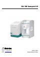

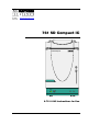


Table of contents
761 SD Compact IC / Instructions for Use 8.761.1043
IV
List of figures
Figure 1: Front of the 761 SD Compact IC ............................................................... 3
Figure 2: Rear panel 761 SD Compact IC ................................................................ 4
Figure 3: Connection schematic for 761 SD Compact IC ........................................ 5
Figure 4: Connectors for capillaries........................................................................ 13
Figure 5: PEEK couplings....................................................................................... 13
Figure 6: Connecting the filter unit PEEK ............................................................... 14
Figure 7: Position of the detector block 40 ............................................................ 15
Figure 8: Pump tubing for regenerant path ............................................................ 21
Figure 9: Flow schematic regenerant flow.............................................................. 22
Figure 10: Pump tubing for sample path.................................................................. 24
Figure 11: Flow schematic sample stream............................................................... 25
Figure 12: Rear panel ............................................................................................... 27
Figure 13: Setting the mains voltage........................................................................ 29
Figure 14: Connection of precolumn and separating column.................................. 41
Figure 15: Components of the pump head .............................................................. 94
Figure 16: Replacement of the piston seal 76.......................................................... 94
Figure 17: Components of inlet valve 77 and outlet valve 78 .................................. 97
Figure 18: Assembling the suppressor .................................................................. 101