
Manual

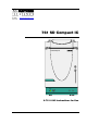


Table of contents
761 SD Compact IC / Instructions for Use 8.761.1043
I
Table of contents
1 Introduction ................................................................ 1
1.1 Instrument description ................................................................................1
1.2 Parts and controls .......................................................................................3
1.2.1 Front view ........................................................................................................... 3
1.2.2 Rear view ............................................................................................................ 4
1.2.3 Connection schematic ....................................................................................... 5
1.3 Information on the Instructions for Use .....................................................7
1.3.1 Organisation ....................................................................................................... 7
1.3.2 Notation and pictograms.................................................................................... 8
1.4 Safety notes .................................................................................................9
1.4.1 Electrical safety................................................................................................... 9
1.4.2 General precautionary rules ............................................................................... 9
2 Installation ............................................................... 10
2.1 Flow chart ..................................................................................................10
2.2 Setting up the instrument..........................................................................11
2.2.1 Packaging......................................................................................................... 11
2.2.2 Check................................................................................................................ 11
2.2.3 Location ............................................................................................................ 11
2.3 Description of the connections.................................................................12
2.3.1 Connection of capillaries/tubing ...................................................................... 12
2.3.2 Connection between capillaries/tubing............................................................ 13
2.3.3 Filter unit PEEK ................................................................................................. 14
2.4 Connection of the detector block .............................................................15
2.5 Installation of the MPak cabinet and connection of the drain tubes ......16
2.5.1 Installing the MPak cabinet .............................................................................. 16
2.5.2 Drain tube for inner compartment.................................................................... 16
2.5.3 Drain tube for MPak cabinet............................................................................. 16
2.6 Installing the eluent path ..........................................................................17
2.6.1 High-pressure pump – Removing the transport security screws .................. 17
2.6.2 Connection MPak → high-pressure pump ...................................................... 17
2.6.3 Connection high-pressure pump → injection valve ........................................ 18
2.6.4 Connection injection valve → suppressor ....................................................... 19
2.6.5 Connection suppressor → detector................................................................. 19
2.6.6 Connection detector → suppressor................................................................. 19
2.6.7 Connection suppressor → waste..................................................................... 20
2.7 Installing the regenerant path...................................................................20
2.7.1 Fitting the pump tubing for regenerant ............................................................ 20
2.7.2 Connection regenerant-MPak → pump tubing → suppressor → waste ........ 21
2.8 Installing the sample path.........................................................................23
2.8.1 Fitting the pump tubing for sample.................................................................. 23
2.8.2 Connection sample vessel → pump tubing → injection valve → waste ........ 24
2.9 Connecting the 766 IC Sample Processor...............................................26
2.9.1 Installing the 766 IC Sample Processor ........................................................... 26
2.9.2 Connecting the 766 IC Sample Processor....................................................... 26
2.10 Fitting the rear panel .................................................................................27
2.11 Mains connections ....................................................................................28
2.11.1 Setting the mains voltage................................................................................. 28
2.11.2 Fuses ................................................................................................................ 29
2.11.3 Mains cable and mains connection ................................................................. 29
2.11.4 Switching the instruments on/off...................................................................... 29