
Manual

2.8 Installing the sample path
761 SD Compact IC / Instructions for Use 8.761.1043
25
2 Connection pump tubing - injection valve
• The sample is forced into the injection valve via the connec-
tion capillary 47.
• Detach the connection capillary 47 with the two pressure
screws 50 from the outlet of the injection valve and from the
opening in the door (it is fitted there only for delivery pur-
poses).
• Screw the ends of the connection capillary 47 to the inlet of
the injection valve and to the PEEK coupling 65 on the right-
hand end of the pump tubing (flow outlet) using one pressure
screw 50 (see Figure 11).
3 Connection injection valve - waste container
The connection capillary 48 routes the sample from the injection
valve into the waste:
• Connect the supplied PTFE capillary 6.1803.030 with a pres-
sure screw 50 6.2744.010 to the outlet of the injection valve.
• Route the other end at the rear out of the 761 SD Compact IC
into the waste container. Wait until after the rear panel has
been fitted to cut it to size (see Section 2.10).
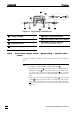
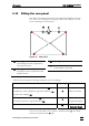
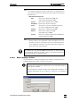
Figure 11: Flow schematic sample stream
3 Aspirating tubing
for sample
47 Connection capillary
PTFE capillary 6.1831.030, connection
pump tubing - injection valve
48 Connection capillary
PTFE capillary 6.1831.030, connection
injection valve - waste container
50 Pressure screw 6.2744.010
63 PEEK coupling 6.2744.030
64 Pump tubing 6.1826.110 for sample
65 PEEK coupling 6.2744.160
with tubing security device
The sample stream should be routed into a waste container down-
stream of the injection valve (see Section 2.8.2.).
50
3
63
65
47
50
64
48