
Manual

2 Installation
761 SD Compact IC / Instructions for Use 8.761.1043
24
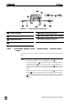
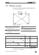
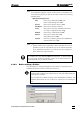
Figure 10: Pump tubing for sample path
57 Tubing cartridge
58 Pressure lever
59 Snap-action lever
62 Stopper orange-yellow
63
PEEK coupling 6.2744.030
64
Pump tubing 6.1826.110 for sample
65
PEEK coupling 6.2744.160
with tubing security device
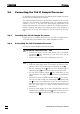
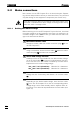
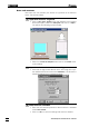
2.8.2 Connection sample vessel → pump tubing → injection valve
→ waste
Proceed as follows in order to make the connections for the sample
path:
1 Connection Sample vessel - pump tubing
The sample is aspirated with the aspirating tubing 3:
• The aspirating tubing 3 is routed through the "feedthrough for
aspirating tubing" 2 out of the front door into the sample ves-
sel. It is fixed in position on the feedthrough 2 with a rotary
nipple (see Section 2.9.2 if using the 766 IC Sample Proces-
sor).
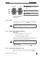
• Detach the other end of the aspirating tubing 3 with pressure
screw 50 from the injection valve (it is fitted there only for de-
livery purposes) and screw it firmly onto the PEEK coupling
63 on the left-hand end of the pump tubing (flow inlet) (see
Figure 11).
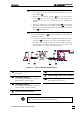
65
64
62
59
63
57
58
62