
Manual

2 Installation
761 SD Compact IC / Instructions for Use 8.761.1043
22
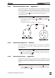
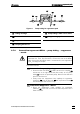
3 Connection MPak pump tubing
The regenerant MPak and pump tubing are connected using the
"tubing connection to MPak" 23 6.1837.000:
• First connect the end which is to be connected to the pump
tubing!
• Pressure screw 52 4.422.4510 and coupling 55 4.455.4500
are already pre-fitted on the "tubing connection to MPak" 23
6.1837.000. Screw this coupling 55 4.455.4500 onto the cou-
pling 60 6.2744.110 plugged onto the left-hand end of the
pump tubing (flow inlet).
• Latch the other end of the "tubing connection to MPak" 23
6.1837.000 at the outlet of the regenerant MPak.
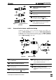
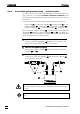
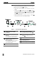
Figure 9: Flow schematic regenerant flow
23 Tubing connection to MPak
6.1837.000
45 Suppressor inlet capillary for re-
generant
PTFE capillary, permanently attached
to the suppressor, labelled "H2SO4"
46 Suppressor outlet capillary for re-
generant ("Waste")
PTFE capillary, permanently attached
to the suppressor; leads in to the
waste, labelled "Waste"
50 Pressure screw 6.2744.010
52 Pressure screw 4.422.4510
for "tubing connection to MPak" 23
55 PEEK coupling 4.455.4500
Coupling for "tubing connection to
MPak" 23
56 Filter unit PEEK 6.2821.120
60 Coupling 6.2744.110
61 Pump tubing 6.1826.110 for H
2
SO
4
52
60
50
46
23
55
56
61
45
60