
Manual
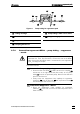

2.7 Installing the regenerant path
761 SD Compact IC / Instructions for Use 8.761.1043
21
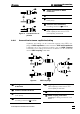
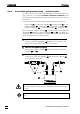
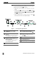
Figure 8: Pump tubing for regenerant path
57
Tubing cartridge
58
Pressure lever
59
Snap-action lever
60
Coupling 6.2744.110
61
Pump tubing 6.1826.110 for H
2
SO
4
62
Stopper orange-yellow
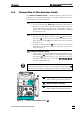
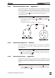
2.7.2 Connection regenerant-MPak → pump tubing → suppressor
→ waste
The connections to the pump tubing, suppressor and waste must be
connected first. Then, and not before, connect the end at the MPak
outlet. If the end at the MPak outlet is connected first, the regenerant
(H
2
SO
4
) will begin to escape.
Proceed as follows:
1 Connection Pump tubing - Suppressor
• Screw the filter unit PEEK 56 6.2821.120 onto the coupling 60
6.2744.110 at the right-hand end (flow outlet) of the pump
tubing 61 fitted in the peristaltic pump. Note the flow direction
arrow on the filter unit.
• Firmly screw the "suppressor inlet capillary for regenerant
("H2SO4")" 45 onto the filter unit 56 with a pressure screw 50
6.2744.010 (see also Section 2.3.3).
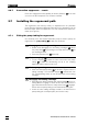
2 Connection Suppressor - Waste
• Route the "suppressor outlet capillary for regenerant
("Waste")" 46 at the rear out of the 761 SD Compact IC into a
waste container.
58
60
62
57
60
61
59
62